


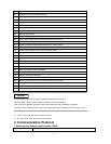
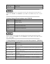
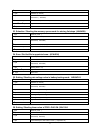
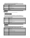

47
1
st
byte Start bit ( AAH )
2
nd
byte Address (0—0XFE)
3
rd
byte
Command
(
48H/49H
)
From 4
th
to 13
th
byte LIST file name (ASSIC code )
From 14
th
to 25
th
byte System reserve
26
th
byte Sum code
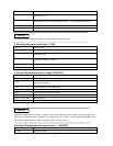
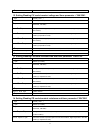
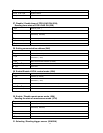
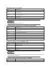
23. Selection / Reading the memory space mode for storing list steps. (4AH/4BH)
1
st
byte Start bit ( AAH )
2
nd
byte Address (0—0XFE)
3
rd
byte
Command
(
4AH/4BH
)
4
th
byte partition mode (1 | 2 | 4 | 8)
From 5
th
to 25
th
byte System reserve
26
th
byte Sum code
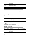
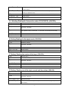
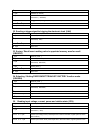
24. Save / Get list file in appointed area.. (4CH/4DH)
1
st
byte Start bit ( AAH )
2
nd
byte Address (0—0XFE)
3
rd
byte
Command
(
4CH/4DH
)
4
th
byte Storing area 1 ~ 8)
From 5
th
to 25
th
byte System reserve
26
th
byte Sum code
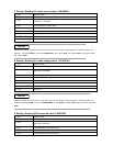
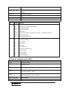
25. Setting / Reading min voltage value in battery testing mode.
(
((
(
4EH/4FH
)
))
)
1
st
byte Start bit ( AAH )
2
nd
byte Address (0—0XFE)
3
rd
byte
Command
(
4EH/4FH
)
4
th
byte The lowest byte of voltage value.
5
th
byte The lower byte of voltage value.
6
th
byte The higher byte of voltage value.
7
th
byte The highest byte of voltage value.
From 8
th
to 25
th
byte System reserve
26
th
byte Sum code
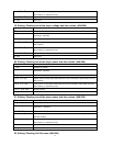
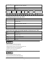
26. Setting / Reading timer value of FOR LOAD ON (50H/51H
)
))
)
1
st
byte Start bit ( AAH )
2
nd
byte Address (0—0XFE)
3
rd
byte
Command
(
50H/51H
)
4
th
byte The lowest byte of time value in timer. (1 represent 1S)