


51
If Load is not in protection state, users could do the calibration operation.
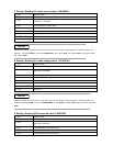
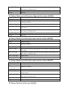
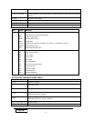
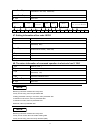
37. Getting the calibration mode state
(
((
(
61H
)
))
)
1
st
byte Start bit ( AAH )
2
nd
byte Address (0—0XFE)
3
rd
byte
Command
(
61H
)
4
th
byte Calibration protection state
From 5
th
to 25
th
byte System
26
th
byte Sum code
NOTE
Represent calibration protection state by one byte. Each byte is defined as:
From high to low
7 6 5 4 3 2 1 0
0 byte
:
protection state
,
0 represent not in the protection state
,
1 represent in protection state.
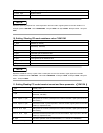
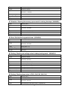
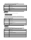
38. Calibrate voltage value
(
((
(
62H
)
))
)
1
st
byte Start bit ( AAH )
2
nd
byte Address (0—0XFE)
3
rd
byte
Command
(
62H
)
4
th
byte
Voltage calibration point
(
1~4
)
From 5
th
to 25
th
byte System reserve
26
th
byte Sum code
NOTE
Current calibration standard points have four: 1, 2, 3,4.
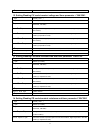
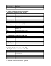
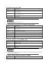
39. Sending the actual input voltage to calibration program
(
((
(
63H
)
))
)
1
st
byte Start bit ( AAH )
2
nd
byte Address (0—0XFE)
3
rd
byte
Command
(
63H
)
4
th
byte The lowest byte of actual voltage
5
th
byte The lower byte of actual voltage
6
th
byte The higher byte of actual voltage.
7
th
byte The highest byte of actual voltage.
From 8
th
to 25
th
byte System reserve
26
th
byte Sum code