


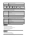

50
later location)
From 12
th
to 15
th
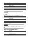
byte Actual input power value (Lower bytes are in the front location, higher bytes are in the later
location)
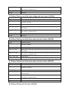
16
th
byte Operation state register
From 17
th
to 18
th
byte Demand state register
From 19
th
to 25
th
byte System reserve
26
th
byte Sum code
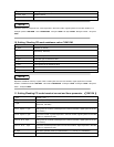
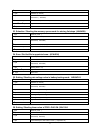
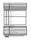
BIT Signal Meaning
0
1
2
3
4
5
6
CAL
WTG
REM
OUT
LOCAL
SENSE
LOT
Operation state register
Calculate the new demarcate coefficient
Wait for trigger signal
Remote control mode
Output state
LOCAL button state (0 is represent “not in effect “,1 is represent ‘in effect “)
Remote testing mode
FOR LOAD ON timer state
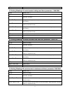
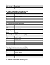
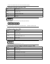
0
1
2
3
4
5
6
7
8
9
RV
OV
OC
OP
OT
SV
CC
CV
CP
CR
Demand state register
Input reverse voltage
Over voltage
Over current
Over power
Over temperature
Not connect remote terminal
Constant current
Constant voltage
Constant power
Constant resistance
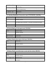
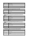
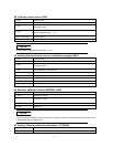
36. Enter the calibration mode
(
((
(
60H
)
))
)
1
st
byte Start bit ( AAH )
2
nd
byte Address (0—0XFE)
3
rd
byte
Command
(
60H
)
4
th
byte Calibration mode select(0:disable;1:enable)
5
th
byte
Calibration password
(
0X85H
)
6
th
byte
Calibration password
(
0X11H or 0X12H
)
From 7
th
to 25
th
byte System reserve
26
th
byte Sum code
NOTE