


49
1
st
byte Start bit ( AAH )
2
nd
byte Address (0—0XFE)
3
rd
byte
Command
(
58H/59H
)
4
th
byte
Trigger mode
(0:Keypad,1 External,2.command)
From 5
th
to 25
th
byte System reserve
26
th
byte Sum code
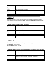
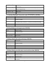
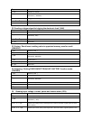
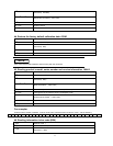
32. Sending a trigger signal to trigging the electronic load. (5AH)
1
st
byte Start bit ( AAH )
2
nd
byte Address (0—0XFE)
3
rd
byte
Command
(
5AH
)
From 4
th
to 25
th
byte System reserve
26
th
byte Sum code
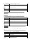
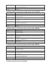
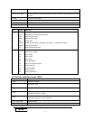
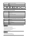
33. Saving / Recall user’s setting value in appointed memory area for recall.
(5BH/5CH)
1
st
byte Start bit ( AAH )
2
nd
byte Address (0—0XFE)
3
rd
byte
Command
(
5BH/5CH
)
4
th
byte Storing area ( )
From 5
th
to 25
th
byte System reserve
26
th
byte Sum code
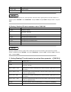
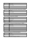
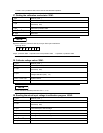
34. Selecting / Getting FIXED/SHORT/TRAN/LIST/ BATTERY function mode.
(5DH/5EH)
1
st
byte Start bit ( AAH )
2
nd
byte Address (0—0XFE)
3
rd
byte
Command
(
5DH/5EH
)
4
th
byte Work mode (0:FIXED,1:SHORT, 2:TRANSITION,3:LIST,4: BATTERY)
From 5
th
to 25
th
byte System reserve
26
th
byte Sum code
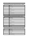
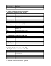
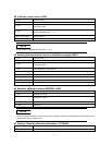
35. Reading input voltage, current, power and relative state. (5FH)
1
st
byte Start bit ( AAH )
2
nd
byte Address (0—0XFE)
3
rd
byte
Command
(
5FH
)
From 4
th
to 7
th
byte Actual input voltage value (Lower bytes are in the front location, higher bytes are in the
later location)
From 8
th
to 11
th
byte Actual input current value (Lower bytes are in the front location, higher bytes are in the