


118
LAN
cable
Ethernet
RS-232C
cable
Video cable
(RCA)
External
device
output
External
device
input
Camera
Dc In
In Out
100/10BT
CC1
RS232C
Video In
Ethernet
CC2 V1 V2 V3 V4
Slot-A
Slot-B
12 21
VB101
Ethernet
Sensor A
Lighting unit
VC-C4R
Power
supply
unit
Lighting unit
ON/OFF
Camera control
and video images
Door opening signal
Sensor B
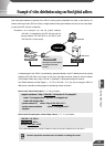
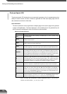
Connector Attached Cable
Sensors mounted on the door
In1
Lighting unit via the power supply unit
Out1
Video cable for the VC-C4R camera
V1
Control cable for the VC-C4R camera
CC1
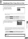
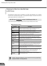
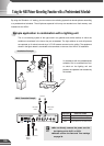
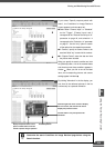
Using the Still Picture Recording Function Linked to an External Device
This is a monitoring system in which the lighting unit needed to take pictures switches on when the
door opens and the VC-C4R camera mounted on the ceiling captures still pictures. The equipment
shown in the figure below is connected to the terminals on the rear of the VB101 at installation.
Sample application in combination with a door-opening sensor and lighting unit
By using the "External Device Input 1/2" setting and connecting devices such as sensors and switches to
the VB101, you can construct a monitoring system that operates in response to external events. The still
pictures captured in this way are recorded on a flash memory card inserted into the VB101.
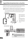
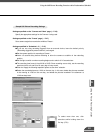
Installation Example
When the door opens and
Sensor B moves away from
sensor A, external device
input In1 generates an ON
event.
In response to this event,
Out1 is controlled to switch
on the lighting unit and
images of the entrance are
captured and recorded by
the camera.
VB101 Connection Example
c
Note
● Do not directly connect the power cord for
the lighting unit to OUT1 or OUT2.
● Please confirm the Date and Time settings
on page 39.