


16
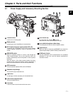
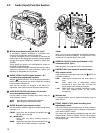
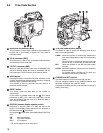
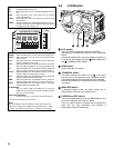
OUTPUT SEL (output signal selection) switch
Used to switch the signals output from the VIDEO OUT and
MON OUT connectors.
MEM: In EE (recording) mode, video from the camera is
output. In VV (playback) mode, playback signal
from a P2 card is output.
CAM: Video from the camera is output constantly.
OFF: Video is not output, and the video camera-
recorder operates in power-saving mode.
Note that the audio output is synchronised with the video.
For types of video outputs, see [4-9-2 Selecting Video
Output Signals].
REW (rewind) button and lamp
During pause, this button performs a fast-reverse playback
with the lamp blinking.
During playback, it performs an approximately 4C fast-
reverse playback with the PLAY and REW lamps blinking.
If this button is pressed when playback is paused, the start
of the clip being played back is located in pause mode.
FF (fast forward) button and lamp
During pause, this button is used to perform fast playback
with the lamp blinking.
During playback, it performs an approximately 4C fast
playback with the PLAY and FF lamps blinking.
If this button is pressed when playback is paused, the start
of the next clip is located in pause mode.
STOP button
This button stops playback.
PLAY/PAUSE button
This button is used to view playback using the viewfinder
screen or a color video monitor. The lamp comes on when
playback starts.
In playback mode, this button pauses (PLAY PAUSE)
playback with the lamp blinking.
REC button
Pressing this button starts recording, and pressing again
stops recording.
This button has the same function as the REC START/
STOP button and the VTR button at the lens.
It may be disabled with the recording protection button.
REC protection button
This button disables the REC button on the handle.
ON: The REC button is enabled.
OFF: The REC button is disabled.
P2 CARD STATUS LED
This LED indicates the recording and playback status of
each card.
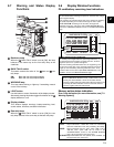
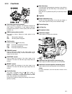
Slide lock button
Used to open the slide-out door for inserting P2 cards. While
depressing this button, slide the door to the left.
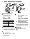
USB 2.0 connector
A USB 2.0 cable is connected here. (To be supported in the
near future.)
GENLOCK IN connector
This connector is used to input a reference signal when the
camera unit is gen-locked, or when the time code is
externally locked. If VIDEO is selected for the menu option
REC SIGNAL, the connector can be used to record actual
signals. The menu option REC SIGNAL is found on the
SYSTEM MODE screen on the SYSTEM SETTINGS page.
<Notes>
z The reference input signal must be a standard VBS
(Video Burst Sync).
z If you need to synchronise the input signal with the AJ-
SPX900E when “VIDEO” is selected for the REC SIGNAL,
set the menu option GENLOCK to “EXT”. The option
GENLOCK is found on the GENLOCK screen, which is
accessible from the SYSTEM SETTING page.
MON OUT (monitor output) connector
This connector outputs the video signal to the monitor. The
video signals linked to the setting of the OUTPUT SEL
switch are output from here. Through an internal menu
option, the characters can be superimposed independently
of the VIDEO OUT connector. For more information, see [4-
9-2 Selecting Video Output Signals].
Connector cover
This cover must be removed in order to attach the optional
connector 1394. For directions on attaching the connector,
see the instruction manual for the optional connector 1394.
(To be supported in the near future.)
ECU REMOTE (remote control) connector
The extension control unit AJ-EC3E (optional accessory) is
connected here.
VIDEO OUT (video signal output) connector
This connector outputs video signals. The video signals
linked to the setting of the OUTPUT SEL switch are output
from here.