


92
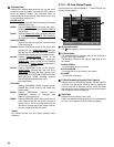
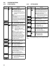
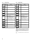
8-2 SYSTEM SETTING
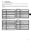
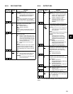
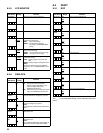
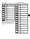
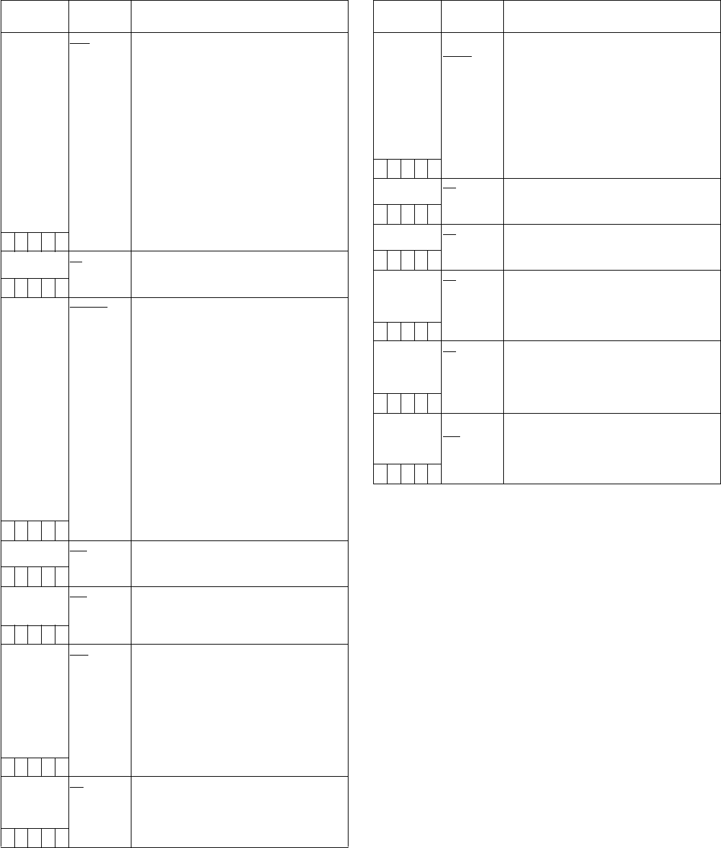
8-2-1 SYSTEM MODE 8-2-2 OPTION MODE
The ____ in the Adjustable Range column indicates the preset
mode.
Items/
Data Saved
Adjustable
Range
Remarks
REC SIGNAL CAM
VIDEO
1394
Select video input signals.
CAM
Record the signal from the camera
VIDEO:
Record the signal from the
GENLOCK IN terminal
1394: Record the signal from the 1394
input terminal (when the optional unit
is attached. *To be supported in the
near future.)
<Notes>
z After the power has been turned OFF, this
setting defaults to CAM when the power is
turned ON again.
z With VIDEO selected, to synchronise this
camera-recorder to the video signal (VBS)
that is input to the GENLOCK IN terminal,
the GENLOCK item in [8-2-6 GENLOCK]
must be set to EXT.
–CUFE
CAMERA
MODE
50I
25P
Switch the operating mode of the camera.
50i: Camera operates in 50i mode.
25P: Camera operates in 25P mode.
SCUFE
V.RES (25P) INTRLCE
PROG.
Set the vertical resolution when the 25P
mode is selected.
INTRLCE:
Lines are mixed. Natural images
can be obtained.
PROG. : Lines are not mixed. Complete
progressive images can be
obtained when images are edited
after shooting.
<Note>
When PROG. is selected, images are
recorded as progressive segmented frame
images, which enables complete
progressive editing. However, adding
Vertical Detail (V.DTL) produces unnatural
images. Therefore, we recommend using
the camera with V.DTL set to 0. (Sufficient
vertical response is maintained in the
images after the progressive editing even
when V.DTL is set to 0.)
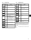
SCUFE
ASPECT 16:9
4:3
Select the aspect ratio for recording.
16:9: Record in <16:9> aspect ratio.
4:3: Record in <4:3> aspect ratio.
–CUFE
REC MODE 50M
25M
DV
Select the recording mode.
50M: Record in DVCPRO50 format.
25M: Record in DVCPRO format.
DV: Record in DV format.
–CUFE
REC TALLY RED
GREEN
CHAR
Select the method of displaying the
recording status of the camera-recorder
when controlling the equipment connected
to 1394 (scheduled to be supported soon).
The recording status of the connected
equipment is displayed by the red tally lamp
on the camera-recorder.
RED: The red tally lamp lights up.
GREEN
:The green tally lamp lights up.
CHAR
: The VF displays [REC] in characters.
–CUFE
ACCESS LED ON
OFF
Select whether or not to enable illumination
of the P2 card access LEDs.
ON: Enable the P2 card access LEDs to
light up for card status indications.
OFF: LEDs remain off.
–CUFE
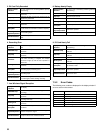
Items/
Data Saved
Adjustable
Range
Remarks
P.O FF G PS
DATA
HOLD
CLEAR
Select whether or not to hold the UMID GPS
position information while the power is
turned off, thereby keeping this information
as status data holding the previous value
until the power is turned on again, which
enables a new measurement to start.
HOLD
: Hold and save the data.
CLEAR
Clear the data when the power is
turned off, and save zero (No-Info)
from the next power-on until a new
measurement is completed.
–CUF–
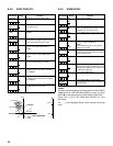
SDI METADATA ON
OFF
Select whether or not to output metadata
(UMID) to the SDI (when the optional AJ-
YA902AG is attached).
–CUF–
SDI EDH ON
OFF
Select whether or not to add an error
detection flag to the SDI output (when the
optional AJ-YA902AG is attached).
–CUF–
SAVE SW (AUD
OUT)
ON
OFF
Select whether or not to forcibly disable the
audio output when the SAVE ON/OFF
switch is set to [ON].
ON: Disable audio output.
OFF: Enable audio output.
–CUF–
SAVE SW (LCD) ON
OFF
Select whether or not to automatically turn
off the LCD monitor when the SAVE ON/
OFF switch is set to [ON].
ON: Turn off LCD monitor.
OFF: Do not turn off LCD monitor.
–CUF–
SAVE SW (SDI) ON
OFF
Select whether or not to automatically
disable the SDI output when the SAVE ON/
OFF switch is set to [ON].
ON: Disable SDI output.
OFF: Enable SDI output.
–CUF–