


16
2. CONTROLS, INDICATORS AND CONNECTORS
PUSH
LINE OUT
Y/C OUT
CH-1
CH-2
MONITOR OUT
FRONT
AUDIO IN
LENS
ewq
r
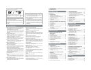
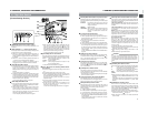
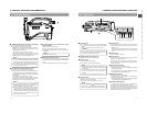
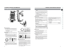
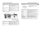
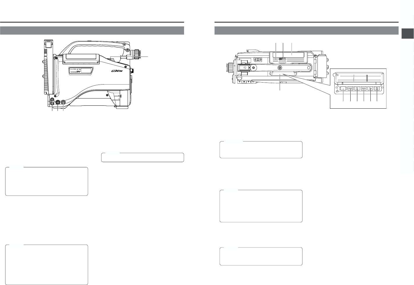
2-3 Left Side Section
1
[MONITOR OUT] Monitor output connector (BNC)
● Composite video signal output connector.
● Video signals with setup level are output.
(Whether or not setup level output should be enabled or
disabled can be selected with the SETUP item on the
AUDIO/VIDEO menu screen.)
Camera mode: The camera image is output.
VTR mode: The playback image is output in the VTR
playback mode. When a DV signal (IEEE1394) is input,
the EE image of the input video signal is output.
MEMO:
● When the OUTPUT CHAR. item on the OTHERS
(1/2) menu screen is set to ON, the same on-screen
indications as those on the viewfinder will be shown
on the external monitor. (Black and white indications)
● The setup signal can be selected also for the EE
output signal of the DV input.
2
[Y/C OUT] Y/C output connector (4-pin)
● Output connector for separate YC video signal.
● Video signals with setup level are output. (Whether or
not setup level output should be enabled or disabled can
be selected with the SETUP item on the AUDIO/VIDEO
menu screen.)
Camera mode: The camera image is output.
VTR mode: The playback image is output in the VTR
playback mode. When a DV signal (IEEE1394) is input,
the EE image of the input video signal is output.
MEMO:
● When the ASPECT RATIO item on the CAMERA
OPERATION menu screen is set to LETTER, 16:9
aspect ratio distinction ID signal is output.
● When the OUTPUT CHAR. item on the OTHERS
(1/2) menu screen is set to ON, the same on-screen
indications as those on the viewfinder will be shown
on the external monitor. (Black and white indications)
● The setup signal can be selected also for the EE
output signal of the DV input.
3
[CH1/CH2 LINE OUT] CH1/CH2 line output
connector (RCA)
Output connector for audio signals.
● Outputs the input audio signal in the Camera mode.
● Outputs the playback audio signal or DV signal in the
VTR mode.
MEMO:
● Alarm sound is not output.
4
Microphone attachment holes
For attaching the microphone holder KA-A50 (optional)
when the optional microphone MV-P615U or MV-P618U is
used.
☞ See “Attaching the Microphone (optional)” on page 31.
17
2. CONTROLS, INDICATORS AND CONNECTORS
STILLSTOPREW
BLANK SEARCH
FF PLAY
we
q
r
!0
o
y
t
u
i
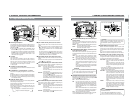
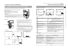
1
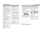
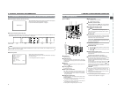
Cassette cover
The cassette cover can be opened by sliding the OPEN
knob
2
. Open this cover to insert or remove a videocassette
from the unit. Normally, this cover should be closed.
CAUTION:
To prevent foreign objects from entering the internal
parts of the VTR unit, do not leave the unit with the
cover open for extended periods of time.
2
[OPEN] Cassette cover lock knob
Slide this knob to open the cassette cover.
3
[EJECT] button
Located inside the cassette cover.
Press this button to eject the videocassette.
MEMO:
● It takes a few seconds before the videocassette is
ejected. Do not close the cassette cover during the
eject operation.
● Do not touch the cassette insertion slot or cassette
during the eject operation. This could result in
damage.
● Eject operation is not possible while the power is off.
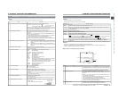
4
Operation cover
Open this cover when operating in the playback mode.
Otherwise, keep this cover closed.
This cover can be opened by sliding it to the side.
MEMO:
When the STOP button (
6
) is pressed in the Camera
mode to set the VTR operation mode indicator to
indicate STOP, playback operations become possible.
5
[PLAY] button
Press to start playback. During still picture playback and
search mode, press this button to return to the normal
playback mode.
* If the auto tracking is active at the moment the play mode
is entered, the playback video will be interfered with digital
noise.
6
[STOP] button
Press to enter the stop mode.
7
[STILL] button
Press to enter the still picture mode during playback, in the
stop mode or in the search mode.
When the still picture mode has continued for about 3
minutes, the unit automatically switches to the stop mode.
(Tape protect mode)
8
[FF] Fast forward button
Press this button to fast forward the tape.
● Pressing this button in the stop or rewind mode initiates
the fast forward mode.
● Pressing this button during playback, still picture playback
or reverse search initiates forward search.
9
[REW] Rewind button
Press this button to rewind the tape.
● Pressing this button in the stop or fast forward mode
initiates the rewind mode.
● Pressing this button during playback, still picture playback
or forward search initiates reverse search.
0
[BLANK SEARCH] button
Press this button to locate blank parts (unrecorded parts)
on the tape, such as the end point of a recording.
Blank search starts when this button is pressed in the stop
mode. When a blank part (unrecorded part) on the tape is
detected, the unit enters the STILL status in the VTR mode
and the Standby status in the Camera mode.
2-4 Top Section