


24
2. CONTROLS, INDICATORS AND CONNECTORS
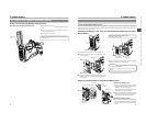
No. Item Contents
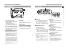
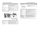
5 Time/Date indication Recorded data are displayed during playback, fast forward, and rewind.
During recording, the data from the DV connector is displayed.
In the stop mode, the current data is displayed.
Whether or not the date and time should be displayed and the display style
are set on the TIME/DATE menu screen.
When the date and time have not been set, the following indication appears.
– – / – – / – – – – : – – : – –
6 Audio sampling frequency indication The audio sampling frequency used for the recording is displayed during
playback.
(32 K, 48 K, 44.1 K)
7 Audio level meter indication Displays the audio level meters during playback.
Whether or not to display this item is set with the AUDIO item on the LCD/
VF (2/2) menu screen.
8 VTR mode indication Indicates the VTR operation status
[STBY, STOP, PLAY, REC, FF, REW, FWD, REV, STL, BSRH, – – – (No
tape loaded)
9 Event display BLANK SEARCH : Indicates that blank search operation is in progress.
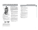
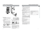
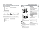
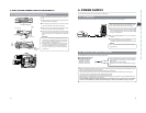
■Magnified Status Indications on the LCD Monitor
The characters on the status screens can be showed alone in magnified size on the LCD monitor.
DISPLAY button
■When the DISPLAY button is pressed while the Status (0, 1,
2, 3) screen is shown in the Camera mode, or a status screen
is shown in the VTR mode, the displayed contents change
every time the DISPLAY button is pressed.
Only image displayed → Characters shown enlarged
Image and characters displayed ←
MONITOR
EDITSEARCH
FILTER
STATUS
SHUTTER
MENU
AUTO IRIS
BACK L
NORMAL
SPOT L
STRETCH
NORMAL
COMPRESS
FULL AUTO BLACK LOLUX
MODE
POWER
ON OFF
VTR
OPEN
VTR
CAM
1
3200K
5600K
5600K
5600K
ND
/
/
ND
2
.3
.4
1
8
1
64
CH-1
AUDIO INPUT
AUDIO SELECT
CH-2
CH-1 CH-2
FRONT
REAR
AUTO
MANUAL
AUDIO
LEVEL
CH-1 CH-2
PULL
OPEN
LCDBRIGHT DISPLAY
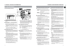
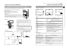
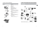
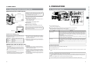
2-6 Indications on the LCD Monitor and in the Viewfinder (Cont’d)
↑
No. Item Contents
1 Audio Lock Indicator Displayed during recording and playback when the audio signal is locked to
the video signal.
2 Time Code Generator Setting Indicator Indicates the set status of the TC GENE switch on the side section.
FREE : TC GENE switch is set to PRESET-FREE RUN MODE.
RECR: TC GENE switch is set to PRESET-REC RUN MODE.
REGN: TC GENE switch is set to REGEN MODE.
3 Drop/Non-drop Indicator Displayed during playback of a tape recorded in drop frame or non-drop
frame mode.
DF : During playback of a tape recorded in drop frame mode.
NDF : During playback of a tape recorded in non-drop frame mode.
1
2
3
CH1
CH2
NDF
FREE H M S F
PLAY
SP
109V
min
48k
OVER
OVER
L
T
C
-
dB
0
1020
3040
∞
12
213
34 34 10
.
e
(U model)
25
2. CONTROLS, INDICATORS AND CONNECTORS
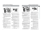
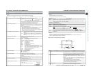
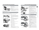
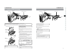
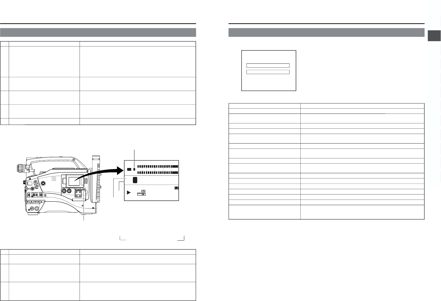
■Alarm Message Display
● The following alarm messages are displayed while the Status(0, 1, 3)
screen is shown in the Camera mode, or a status screen is shown in
the VTR mode.
If an alarm is generated while the Status 2 screen is shown, the Status
0 screen returns to display the alarm.
● When an abnormality occurs in the VTR, a warning message with an
error code is displayed.
Alarm display area
Alarm display area
FAS
–3dB
FAW
I
SD
B
12
.2V
01/02/03
AM
01:23:45
Alarm Indication Contents
PAL INHIBIT Displayed when attempt is made to play back a tape recorded with PAL signal.
REC INHIBIT Displayed when an unrecordable videocassette (the switch on the back of the
cassette is set to “SAVE”) is loaded.
COPY INHIBIT Displayed when attempt is made to record a copy-guarded signal.
LOW VOLTAGE Displayed when remaining battery power becomes low.
TAPE NEAR END Flashes when the remaining tape is 3 minutes or less in the shooting mode. It is
not shown in the playback mode.
TAPE END Displayed when the tape has reached its end.
INVALID TAPE! Displayed when a data tape for PC use or DVC PRO cassette is used. The tape
is ejected.
LP TAPE INVALID! Displayed when attempt is made to playback a tape recorded in the LP mode.
NO TAPE! Displayed when no videocassette is inserted and the VTR trigger button is
pressed.
NO DV SIGNAL! Displayed when there is no input to the DV connector and recording is attempted.
COPY GUARD! Displayed when attempt is made to play back a copy-guarded tape.
CLEANING TAPE! Displayed when a head cleaning tape is inserted.
HEAD CLEANING REQUIRED! Displayed when head is clogged. Head cleaning is necessary.
CLOSE CASSETTE COVER! Displayed when operation is attempted while the cassette cover is open.
OPEN CASSETTE COVER! Displayed when the cassette cover is closed during the eject operation.
VCR WARNING (Error code) Displayed in case abnormalities occur in the VCR, or when condensation occurs
(Example) 7001 in the unit. For details, ☞ see page 88.
DRUM MOTOR FAILURE