


32
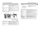
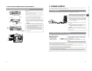
3. BASIC SYSTEM CONNECTIONS AND ADJUSTMENTS
3.
Rear base
mount
4.
Front
base
mount
4.
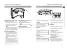
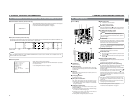
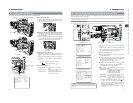
MONITOR
EDITSEARCH
FILTER
STATUS
SHUTTER
MENU
AUTO IRIS
BACK L
NORMAL
SPOT L
STRETCH
NORMAL
COMPRESS
FULL AUTO BLACK LOLUX
MODE
POWER
ON OFF
VTR
OPEN
VTR
CAM
1
3200K
5600K
5600K
5600K
ND
/
/
ND
2
.3
.4
1
8
1
64
CH-1
AUDIO INPUT
AUDIO SELECT
CH-2
CH-1 CH-2
FRONT
REAR
AUTO
MANUAL
AUDIO
LEVEL
CH-1 CH-2
PULL
OPEN
LCDBRIGHT DISPLAY
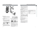
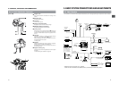
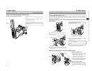
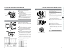
3-6 Attaching the Tripod Base (Provided)
Front mount clip
2.
Safety lever
2.
Lock lever
3.
Pin
1.
Tripod mounting holes
Use the provided KA-550U tripod base to place the camera on
a tripod.
1.
Attach the tripod base on the tripod by using the hole that
balances the unit most optimally.
2.
While pushing the safety lever, pull the lock lever toward
the front until the front mount clip clicks into place.
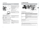
3.
Place the unit on the tripod base by aligning the rear base
mount of the unit with the pin on the tripod base.
4.
Push the unit from the upward direction and slide it toward
the front so that the front base mount of the unit is locked
by the front mount clip of the tripod base as it clicks into
place.
CAUTION:
● The front base mount may be locked while the pin of the
tripod base is not inserted into the hole on the rear base
mount of the unit. Therefore, after mounting, make sure
that these parts are engaged properly.
● When moving the unit mounted on a tripod, any impact
or vibration should be avoided as this may cause the
unit to become detached and to drop from the tripod.
Be sure to remove the unit from the tripod before
transporting it.
33
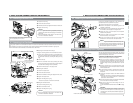
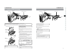
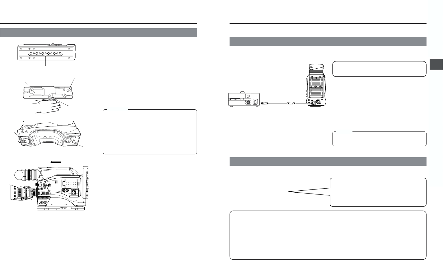
4. POWER SUPPLY
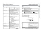
■Flat shape type battery pack
■Anton-Bauer battery pack
●Propack 13/14 Series
●Tr impack 13/14 Series
●Magnum 13/14 Series
●Compack 13/14 Series
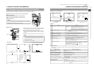
PHONES
DC OUT
DC IN
DV REAR AUDIO IN TALLY
AA-P250
DC cable
AC power adapter
The GY-DV5000 is operable with AC power supply or battery pack.
Use the JVC AA-P250 AC power adapter (max. rated output 12.5 V DC, 3.5 A) as the AC power supply.
1.
After making sure that the power switches of the GY-DV5000
and of the AA-P250 are set to OFF, connect the DC cable
from the AA-P250 to the DC IN connector of the GY-DV5000
as shown in the illustration.
2.
Set the CHARGE/CAMERA switch of the AA-P250 to
CAMERA.
3.
Press the POWER switch of the GY-DV5000 to ON. Power
is supplied to the VTR section and the camera.
*For details, read the instruction manual of the AA-P250.
The GY-DV5000 can be operated with the following battery packs.
● When the DC cable is connected to the DC IN connector, the power supply from the battery pack is interrupted and the power
starts to be supplied through the DC IN connector.
● Do not connect or disconnect the DC cable while operating with a battery pack.
The following symptoms may occur if the DC cable is connected or disconnected while operating with a battery pack.
• The power is cut off for a moment when the DC cable is disconnected.
• Noise to the video and audio signals occurs. Audio signal are muted.
● When operation is continued with DC input after the battery pack capacity has been used up, set the POWER switch to OFF
after the DC power is applied. Then switch ON again.
● If the GY-DV5000 is left with the battery pack attached, a small amount of power is consumed even if the POWER
switch on the GY-DV5000 is set to OFF. Remove the battery pack when the GY-DV5000 is not going to be used.
Do not use any power source with large fluctuations in the
power source voltage, power sources generating noise,
such as ripples or power sources with lower voltage.
4-1 AC Operation
4-2 Battery Pack Operation (Optional)
* An Anton-Bauer battery pack cannot be connected directly
to the GY-DV5000. It is necessary to mount the optional
battery holder.
Battery holder: Anton-Bauer QRQ27
For details on how to mount the battery holder, see page
35.
MEMO:
Do not remove or connect the DC cable while recording is
being performed.