


12
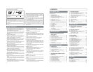
2. CONTROLS, INDICATORS AND CONNECTORS
1
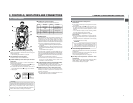
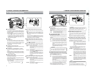
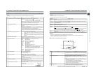
[MONITOR] Audio monitor volume control
Adjusts the volume of the monitoring loudspeaker and
earphone.
2
[EDIT SEARCH +/–] +/– button for edit search
Pressing this button in the record-standby mode plays back
the tape while the button is being pressed.
● While the + button is pressed, playback takes place at
the normal speed. When the button is released, the
standby mode is reengaged at the point where the button
is released.
● While the – button is pressed, playback takes place at
–1 times the normal speed (reverse playback).
When the button is released, the standby mode is
reengaged at the point where the button is released.
3
[STATUS] Status/Menu button
● Pressing this button in the normal screen mode (condition
in which the menu screen is not shown) displays a status
screen in the viewfinder or on the LCD monitor. The
displayed status screen changes each time the button is
pressed.
☞ See “Status Screens” on page 20.
● Pressing this button for more than 1 second in the normal
screen mode displays the menu screen in the viewfinder
or on the LCD monitor. Pressing this button while the menu
screen is displayed in the viewfinder or on the LCD monitor
makes the menu screen disappear.
☞ See “Setting Menu Screens” on page 66.
4
[SHUTTER] Shutter/Menu dial
● Every time this dial is pressed while in the normal screen
mode (when the menu screen is not displayed), the shutter
speed switches between on/off.
● When this dial is turned 1 click up or down in the normal
screen mode, the shutter speed indicator is shown for
about 3 seconds on the LCD monitor or in the viewfinder.
The shutter speed is changed when this dial is turned
while the shutter speed indicator is shown.
☞ See “Adjusting the Shutter Speed” on page 81.
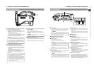
[Camera Setting Section]
GAINGAIN
OUTPUTOUTPUT
CAMCAM
BARSBARS
ONON
OFFOFF
PRSTPRST BA
AUTUTOKNEEOKNEE
WHTWHT.BAL.BAL
MODEMODE
M
LH
MONITOR
EDITSEARCH
FILTER
STATUS
SHUTTER
MENU
AUTO IRIS
BACK L
NORMAL
SPOT L
STRETCH
NORMAL
COMPRESS
FULL AUTO BLACK LOLUX
MODE
POWER
ON OFF
VTR
VTR
CAM
1
3200K
5600K
5600K
5600K
ND
/
/
ND
2
.3
.4
1
8
1
64
AUDIO
LEVE
CH-1 CH-2
r
e
w
q
t
!1
!3
!4
!5
!6
!2
y
u
i
o
!0
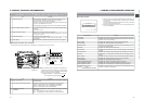
2-2 Right Side Section
● When this dial is turned upward or downward while the
menu screen is displayed, the cursor (
) also moves
upward or downward to allow selection of items in the
menu. To change the setting value of the item, press this
dial. When the setting value starts blinking, turn this dial
upward or downward to change the setting.
☞ See “Setting Menu Screens” on page 66.
5
[AUTO IRIS] Auto iris level switch
This switch selects the automatic iris adjustment reference
value according to the condition in which the camera is used.
BACK L : Under back light (Opens the iris about 1 step
from the standard level.)
NORMAL : Normal condition
SPOT L : Under spotlight (Closes the iris about 1 step
from the standard level.)
☞ See “SWITCH FUNCTIONS” on page 84.
6
[FULL AUTO] Full auto shooting ON/OFF button
and indicator
● This switch toggles the full auto shooting function on and
off.
● The indicator lights when in the full auto mode.
● Full auto shooting combines the auto iris, auto level control
(ALC) to automatically adjust the video signal level and
the white balance to their optimum levels.
The audio recording level will operate in the auto
adjustment mode.
● The iris is placed in automatic mode even if the iris mode
switch of the lens is in manual.
● The gain will vary continuously to the maximum of +18
dB. The shutter speed will vary continuously to the
minimum of 1/240 of a second.
☞ See “Full Auto Shooting (FAS) function” on page 84.
13
2. CONTROLS, INDICATORS AND CONNECTORS
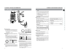
7
[BLACK] Black stretch/black compression switch
Switches the gain for the dark section of the image.
Set to an appropriate position depending on the video signal
to be shot.
STRETCH : By stretching the signal only for the dark
section, contrast in the dark sections of the
image is enhanced.
NORMAL : Standard mode.
COMPRESS: When an entire image is relatively light and
the contrast is low, the gain of the dark
sections is compressed to increase the
contrast.
8
[LOLUX] LOLUX On/Off button
This button toggles the LOLUX mode on and off.
● LOLUX gain gives extremely low light level sensitivity for
special applications. This will result in an increase of 30
dB in the LOLUX mode.
● The gain up value can be selected from the menu.
☞ See page 69.
● LOLUX operation takes priority over normal gain setting.
● If the unit is placed in the LOLUX mode when it is in full
auto shooting mode, the auto level control (ALC) (one of
the full auto shooting functions) will be made inactive, so
that the LOLUX mode is given preference (FAW still
remains active).
☞ See “GAIN BOOST UNDER LOLUX CONDITION” on
page 83.
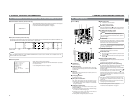
9
[CAM] Camera mode indicator
This indicator lights when the camera is in the Camera mode.
To record the camera image, press the MODE switch
^
to
turn on this indicator. When the power is turned on, the
mode becomes the Camera mode.
0
[VTR] VTR mode indicator
This indicator lights when the camera is in the VTR mode.
To perform VTR playback or input the DV signal from the
DV connector
6
on page 19, press the MODE switch
^
to
turn on this indicator.
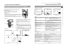
!
[POWER] Power ON/OFF switch
This switch is used to turn the power on and off.
“POFF” is displayed on the LCD monitor or in the viewfinder
when the power is turned off.
*Wait 5 seconds or more before turning the power on again
after it has been turned off.
@
[VTR] Trigger button (Recording Start/Stop)
This button is used to start and stop recording.
(It is interlocked with the VTR trigger button on the front
and the VTR trigger button on the lens section.)
#
[GAIN] Sensitivity selector switch
Electronically boosts the light sensitivity when there is
insufficient illumination on the subject. The boosting level
differs depending on the switch position as follows:
(Factory presets)
L :0 dB (no boosting is applied)
M :9 dB (boosted to approximately 3 times the original)
H : 18 dB (boosted to approximately 8 times the original)
● The boosting level for each switch position can be
changed with the CAMERA OPERATION MENU screen.
☞ See page 69.
The more the boosting level is increased, the more the
resulting image will be noisy.
$
[OUTPUT] Color bar/Camera/Auto knee switch
This switch is used to select the output signal. When the
video signal from the shooting camera is selected, the auto
knee function is available.
CAM. AUTO KNEE ON: Outputs the video signal from the
shooting camera. In this mode, the auto knee function is
available.
CAM. AUTO KNEE OFF: Outputs the video signal from the
shooting camera. In this mode, the auto knee function is
not available.
BARS: Outputs the color bar signal. In this mode, the auto
knee function is not available. Set to this position when
adjusting the video monitor or when recording the color bar
signal. Color bars will not appear when Full Auto is set to
ON or when in the VTR mode.
AUTO KNEE function
When shooting a foreground subject, such as a human
being, etc., with a high-brightness background, if the
brightness level is set for the foreground subject, the
background image will be blurred with white. In such a case,
a clearer background is obtained when the auto knee
function is used.
It is effective especially in the following cases:
● When shooting a human being indoors with a view to the
landscape out through a window.
● When shooting a human being in the shade on a fine
day.
● When shooting a high-contrast scene.
CAUTION:
If a fast moving high-brightness section like a car in
sunlight is shot, the auto knee function may change
the brightness of the entire image along with the motion
of the object. In this case, set the auto knee function to
OFF.
%
[WHT.BAL] White balance switch
Three white balance modes are selectable with this switch.
B : If white balance is performed with the switch in
this position, it will be memorized into B.
A : If white balance is performed with the switch in
this position, it will be memorized into A.
PRST :A non-erasable white balance setting at 3200K.
(PRESET)
● FAW (Full-time Auto White) mode can be set to A, B or
PRESET with the CAMERA OPERATION menu. ☞ See
page 69.
In the FAW mode, video color temperatures are constantly
sampled for automatic adjustment to a proper white
balance.
^
[MODE] Mode switching switch
This is a switch to select either the Camera mode or the
VTR mode. Each time this switch is pressed upward, the
mode is switched to either the Camera mode or the VTR
mode and the CAM indicator
9
or VTR indicator
0
lights
in accordance with the selected mode.
● Select the Camera mode to record the camera image.
● Select the VTR mode to playback or to input the DV signal
from the DV connector
6
on page 19.
● When the power is turned on, the mode becomes the
Camera mode.