


14
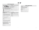
2. CONTROLS, INDICATORS AND CONNECTORS
1
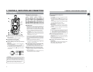
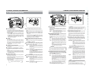
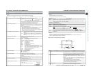
Monitoring loudspeaker
In the Camera mode, the input sound can be EE monitored. In
the VTR mode, the speaker outputs the VTR playback sound.
The sound to be output is selected with the MONITOR
SELECT switch
@
.
● The sound level is adjusted with the MONITOR sound
level button
1
on page 12. The sound from this speaker
is not output if an earphone is plugged into the PHONES
jack
5
on page 18. This speaker also outputs various
warning sounds superimposed on other sound. ☞ See
“Alarm Sounds” on page 89.
2
LCD door
LCD monitor door.
The LCD monitor is located on the inner side of the door.
The LCD monitor can be viewed when this door is opened.
The door can be turned to change the orientation of the
LCD monitor, and it can be rotated so that it can be
accommodated in the main body of the camera.
☞ See page 40.
3
LCD door lock and release knob
To open the LCD door, move this knob in the direction toward
the rear section.
4
[LCD BRIGHT +/–] LCD brightness +/– button
This button is for adjusting the brightness of the LCD monitor
display.
●
Pushing the button in the + direction makes the monitor brighter.
●
Pushing the button in the – direction makes the monitor darker.
● Pushing the +/- buttons simultaneously returns the setting
to the standard setting.
5
[DISPLAY] Display button
This button is for turning the LCD monitor display ON/OFF
and selecting the display mode.
When this button is pressed for a long time, the LCD monitor
display is turned ON or OFF.
Each time this button is briefly pressed while the LCD
monitor display is turned on, the display mode changes as
shown in the following.
Only image displayed → Characters shown enlarged
Image and characters displayed ←
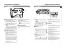
6
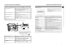
[CH-1 AUDIO LEVEL] CH1 audio level control
Adjust the audio level of the CH1 audio channel with this
control.
● To use this control, set the CH1 AUDIO SELECT switch
8
to “MANUAL”. This control works regardless of the
setting of CH1 FRONT VR item on the AUDIO/VIDEO
menu screen.
To use this control, set the AUDIO LEVEL CH-1 control
switch on the front section (
7
on page 10) to the maximum
(10) position, or set the CH1 FRONT VR item on the
AUDIO/VIDEO menu screen to “DISABLE”.
7
[CH-2 AUDIO LEVEL] CH-2 audio level control
Adjust the audio level of the CH2 audio channel with this
control.
● This control is valid only when the CH-2 AUDIO SELECT
switch
9
is set to “MANUAL”.
8
[CH-1 AUDIO SELECT] CH-1 audio selector switch
This switch is used to select the method for adjusting the
audio level of the CH-1 audio channel.
AUTO : The audio level is held at the reference level
even when sounds greater than the reference
level are input.
The audio level does not increase when the
input level is low.
MANUAL : The audio level can be adjusted with the CH-1
AUDIO LEVEL control
6
or the AUDIO LEVEL
CH-1 control
7
on page 10.
To use the AUDIO LEVEL CH-1 control on the
front section, the CH1 FRONT VR item on the
AUDIO/VIDEO menu screen should be set to
“ENABLE”.
9
[CH-2 AUDIO SELECT] CH-2 audio selector switch
This switch is used to select the method for adjusting the
audio level of the CH-2 audio channel.
AUTO : The audio level is held at the reference level
even when sounds greater than the reference
level are input.
The audio level does not increase when the
input level is low.
MANUAL : The audio level can be adjusted with the CH-2
AUDIO LEVEL control
7
.
MONITOR
EDITSEARCH
FILTER
STATUS
SHUTTER
MENU
AUTO IRIS
BACK L
NORMAL
SPOT L
STRETCH
NORMAL
COMPRESS
FULL AUTO BLACK LOLUX
MODE
POWER
ON OFF
VTR
OPEN
VTR
CAM
1
3200K
5600K
5600K
5600K
ND
/
/
ND
2
.3
.4
1
8
1
64
CH-1
AUDIO INPUT
AUDIO SELECT
CH-2
CH-1 CH-2
FRONT
REAR
AUTO
MANUAL
AUDIO
LEVEL
CH-1 CH-2
PULL
OPEN
LCDBRIGHT DISPLAY
CH-1
AUDIO INPUT
AUDIO SELECT
CH-2
CH-1 CH-2
FRONT
REAR
AUTO
MANUAL
AUDIO
LEVEL
CH-1 CH-2
PULL
OPEN
LCD BRIGHT DISPLAY
i
o
y
u
t
r
q
w
e
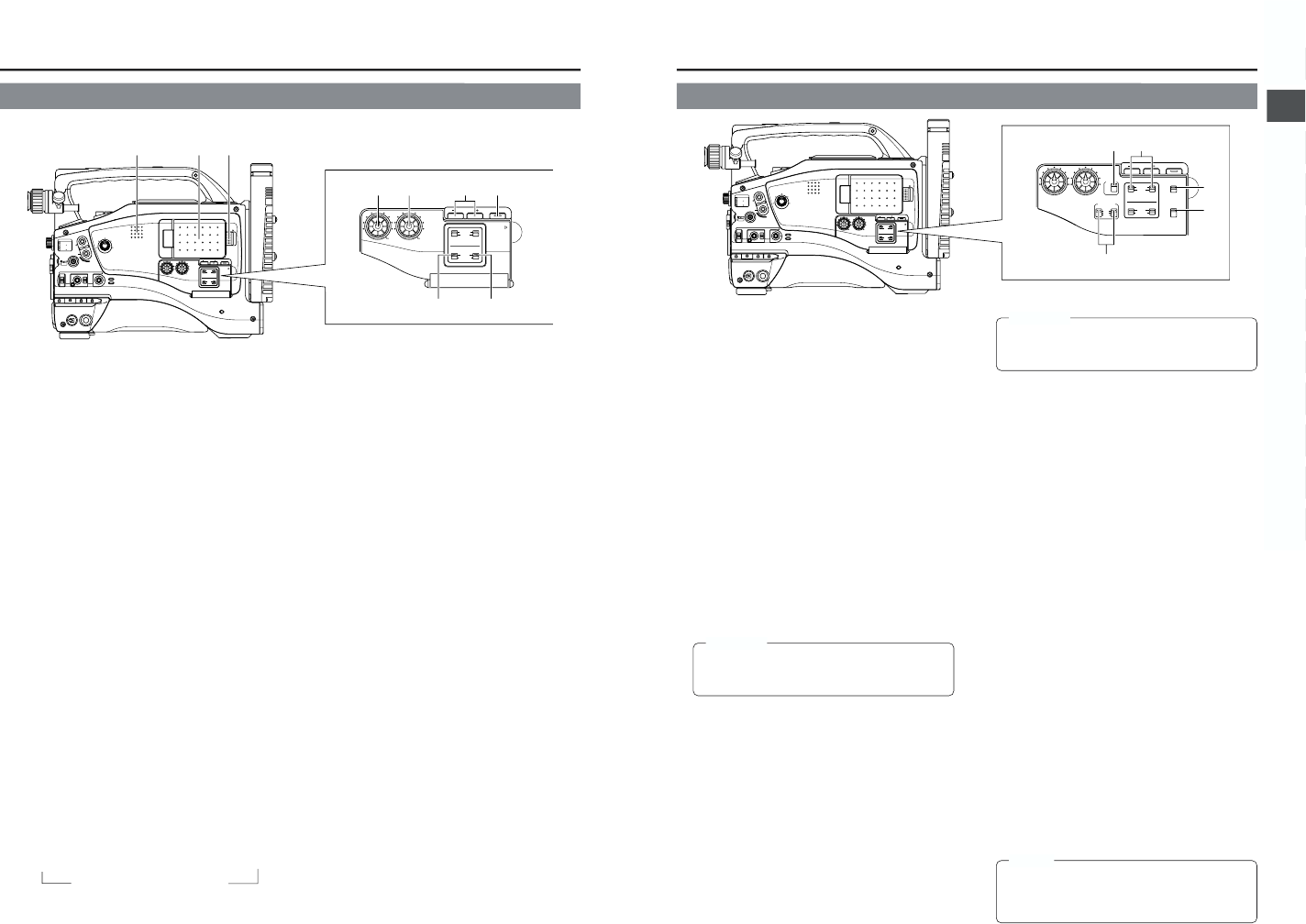
2-2 Right Side Section (Cont’d)
↑
15
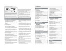
2. CONTROLS, INDICATORS AND CONNECTORS
MONITOR
EDITSEARCH
FILTER
STATUS
SHUTTER
MENU
AUTO IRIS
BACK L
NORMAL
SPOT L
STRETCH
NORMAL
COMPRESS
FULL AUTO BLACK LOLUX
MODE
POWER
ON OFF
VTR
OPEN
VTR
CAM
1
3200K
5600K
5600K
5600K
ND
/
/
ND
2
.3
.4
1
8
1
64
CH-1
AUDIO INPUT
AUDIO SELECT
CH-2
CH-1 CH-2
FRONT
REAR
AUTO
MANUAL
AUDIO
LEVEL
CH-1 CH-2
PULL
OPEN
LCDBRIGHT DISPLAY
COUNTER
CH-1
AUDIO INPUT
AUDIO SELECT
CH-2
CH-1 CH-2
FRONT
REAR
AUTO
MANUAL
TC GENE.
TC
MONITOR
SELECT
AUDIO
LEVEL
AUDIO INPUT
CH-1 CH-2
CH-1
MIX
CH-2
FRONT REAR
LINE
MIC
+48V
PRST
REGEN FREE
REC
UB
LCD BRIGHT DISPLAY
!1
!2
!3
!4
!0
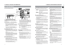
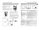
0
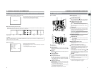
[CH-1/CH-2 AUDIO INPUT] CH-1/CH-2 audio input
selector switch
This switch is used to select the input sound of the CH1 or
CH2 audio channel. It is selected for each of the CH1 and
CH2 channels.
FRONT : The sound from the FRONT AUDIO IN connector
on the front side section is input.
REAR : The sound from the REAR AUDIO IN connector
on the rear side section is input.
!
[FRONT/REAR AUDIO INPUT] Front/rear audio
input signal selector switch.
This switch is used to select the input sound signal from
the FRONT AUDIO IN connector and the REAR AUDIO IN
connector.
LINE : Set to this position when connected to audio
equipment, etc. The reference input level is +4 dBs.
MIC : Set to this position when the microphone is
connected. The reference input level is -60 dBs.
+48V : Set to this position when a microphone requiring
+48 V power supply (phantom microphone, etc.) is
connected. This connector supplies +48 V DC
current.
When using the provided microphone connected
to the FRONT AUDIO IN connector, set the FRONT
AUDIO INPUT switch to this setting.
CAUTION:
When connecting a component that does not require
+48 V power supply, make sure that the switch is not
set to +48V before the component is connected.
@
[MONITOR SELECT] Audio monitor selector switch
This switch is used to select the monitor sound output and
playback sound output from the monitoring loudspeaker
1
or the PHONES
5
jack on page 18.
CH-1 : The CH1 channel audio is output.
MIX : CH1 and CH2 channel audio are output mixed.
When this setting is selected, the menu screen can
be used to select whether the mixed sound or stereo
sound should be output via the PHONES jack.
(AUDIO MONITOR item on the AUDIO/VIDEO
menu screen)
When AUDIO MONITOR in the AUDIO/VIDEO
menu screen is set to “STEREO”, only the audio of
CH-1 is output from the monitoring loudspeaker.
CH-2 : The CH2 channel audio is output.
☞ See “Outputting CH-3, CH-4 Channel Audio” on page 59.
☞ See “AUDIO/VIDEO Menu Screen” on page 72.
View with cover open.
CAUTION:
Make sure to move switches all the way. Do not leave a
switch stopped in a midway position. Noise will be
generated and operation irregularities will occur.
#
[COUNTER] Counter display switch
Selects the contents displayed on the TC counter of the
LCD monitor or in the viewfinder. (This switch works when
the TC/UB item on the LCD/VF (2/2) menu screen is set to
ON.)
TC : Set to this position to display time code values.
UB : Set to this position to display the user’s bits values.
$
[TC GENE.] Time code generator setting switch
Switch for setting the time code generator to preset mode
or regeneration mode. It is also used to select the time code
run mode when the preset mode is selected.
PRST-FREE : The preset mode is selected, and the time
code run mode becomes the FREE run
mode.
Set to this position to record with the time
code or user’s bits set anew (preset). In this
setting, the time code always operates in the
run mode.
* If this setting is used when recording scenes one after
another, the time codes become discontinuous at the
transition points between scenes.
PRST-REC : The preset mode is selected, and the time
code run mode becomes the REC run mode.
Set to this position to record with the time
code or user’s bits set anew (preset). The
time code operates in the run mode during
recording only. If this setting is used when
recording scenes one after another, the time
codes are recorded as continuous time
codes.
REGEN : Regeneration mode, in which the unit reads
existing time codes on the tape and records
time codes in continuation of the existing
ones. Set to this position when you want to
add additional time codes to time codes
already recorded on the tape.
MEMO:
Preset of time code and user’s bits is performed on the
TC/UB/CLOCK menu.
☞ See “TIME CODE OPERATION” on page 62.
☞ See “TC/UB/CLOCK Menu Screen” on page 75.