


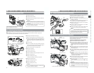

30
3. BASIC SYSTEM CONNECTIONS AND ADJUSTMENTS
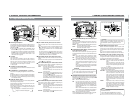
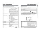
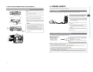
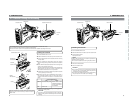
3-2 Attaching the Zoom Lens
CAUTION:
1.
Loosen the mount ring.
2.
Connect the cable connector.
3.
Attach the lens with its pin aligned with the hole in the mount.
4.
Tighten the mount ring.
● Be sure to tighten the mount ring completely. Incomplete
tightening may result in the lens dropping off or disturbed
back focus.
● Set the GY-DV5000's power switch to “OFF” before the
zoom lens is attached or detached.
5.
1.
1.
4.
3.
2.
3.
2.
4.
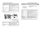
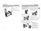
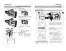
Screw holes for left eye use
Fastening screws
Cap
Cap
HEXAGON WRENCH
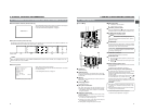
Sliding securing
ring
Stopper
screw
Mounting guide
Viewfinder
mount base
Connector
3-3 Attaching the Viewfinder
■Observing the viewfinder with the left eye
Change the mounting position of the viewfinder mount base.
1.
Loosen the two fastening screws of the viewfinder mount
base with an hexagon wrench (Provided) and then remove
the viewfinder mount base (including the sliding securing
ring).
2.
Remove the cap.
3.
Mount the viewfinder mount base (including the sliding
securing ring) at the screw holes for left eye use and tighten
the screw with the hexagon wrench (Provided).
4.
Attach the removed cap on the right-eye side.
■Attaching the Viewfinder
1.
Loosen the stopper screw.
2.
Connect the cable connector.
3.
Attach the viewfinder with its guide aligned with the shoe.
4.
Tighten the stopper screw.
5.
Tighten the sliding securing ring.
*Reverse the procedure to remove the viewfinder.
■Sliding the viewfinder forward
1.
Loosen the sliding securing ring.
2.
Slide the viewfinder forward.
3.
Tighten the sliding securing ring.
● Set the GY-DV5000’s power switch to “OFF” before the
viewfinder is attached or detached.
By changing the position of the viewfinder mount base on the camera the viewfinder can be observed with either the left or the right
eye.
When shipped from the factory, the viewfinder mount base is attached so that the viewfinder is mounted for right eye use.
After the viewfinder has been attached, the viewfinder can be slid forward.
3.
2.
1.
4.
When unplugging the cable connector, first remove the lens
itself. Then grasp this portion and pull out.
Hole
Pin
2.
1.
3.
Viewfinder
Sliding securing
ring
CAUTION:
31
3. BASIC SYSTEM CONNECTIONS AND ADJUSTMENTS
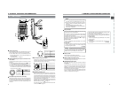
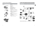
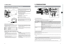
VF
2.
4.
5.
1.3.
6.
Cable clampMicrophone cable
3-4 Attaching the Microphone (Provided)
2,4.
1.
KA-A50
Microphone holder
MV-P615U/MV-P618U
FRONT AUDIO INPUT Microphone cable
3.
5.
6.
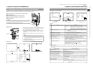
3-5 Attaching the Microphone (Optional)
With the optional KA-A50 microphone holder, the optional
microphones MV-P615U (phantom microphone) and MV-P618U
(phantom microphone) can be used.
<Attaching the Microphone Using KA-A50>
1.
Secure the microphone holder with 2 screws.
2.
Turn the small knob located on the outer side of the
microphone holder counterclockwise to loosen it, and loosen
the large knob located on the inner side in the same way.
Rotate the large knob fully counterclockwise to open the
holder.
3.
Attach the microphone to the microphone holder at the
designated place so that the microphone does not interfere
with the cassette cover.
4.
Set the microphone holder so that the height is level, and
tighten the inside and outside knobs to secure the
microphone.
5.
Connect the microphone cable to the FRONT AUDIO IN
connector.
● When the microphone is connected to REAR AUDIO IN
connector on the rear panel, set the CH-1 or CH-2 AUDIO
input selector switch to REAR.
6.
Secure the microphone cable using the cable clamp located
on the front side of the microphone holder.
7.
Make sure to perform the correct settings for use of a
phantom microphone.
☞ See “FRONT/REAR AUDIO INPUT switch
!
” on page
15.
CAUTION:
● When the light mounted on the camera is used at the
same time, if the microphone in use has a long sound
collecting section, the microphone’s shadow may appear
in the image.
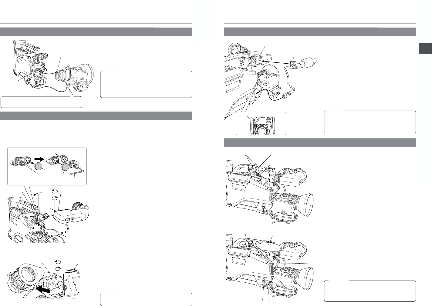
When attaching the viewfinder for use with the left eye, the
provided microphone cannot be attached. In this case, use
the optional microphone holder KA-A50 and microphones
MV-P615U/618U (phantom microphone).
Connect the provided microphone to the viewfinder. The
provided microphone is a phantom microphone.
1.
Loosen the stopper screw on the viewfinder.
2.
Attach the microphone to the attachment guide on the
viewfinder as illustrated.
3.
Confirm that there is no gap between the microphone and
the viewfinder, and then tighten the stopper screw.
4.
Tighten the screw on the microphone. The microphone
should be firmly attached.
5.
Connect the cable from the microphone to the FRONT
AUDIO IN connector on the camera.
6.
Secure the microphone cable using the cable clamp
provided on the front side of the microphone holder.
MEMO: