


64
10. TIME CODE OPERATION
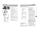
The GY-DV5000 also incorporates a time code reader. Therefore, when the unit enters record mode from record-standby mode, it
can read the time code data recorded on the tape and record time codes in continuation of the existing data. The recorded user’s
bit data are identical to the user’s bit data recorded on tape.
● However, approximately ±1-frame variations may occur in scene accuracy.
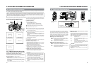
To enable this function, set the time code related switches as follows before starting recording.
OPEN
CH-1
AUDIO INPUT
AUDIO SELECT
CH-2
CH-1 CH-2
FRONT
REAR
AUTO
MANUAL
AUDIO
LEVEL
CH-1 CH-2
PULL
OPEN
LCDBRIGHT DISPLAY
COUNTER
CH-1
AUDIO INPUT
AUDIO SELECT
CH-2
CH-1 CH-2
FRONT
REAR
AUTO
MANUAL
TC GENE.
TC
MONITOR
SELECT
AUDIO
LEVEL
AUDIO INPUT
CH-1 CH-2
CH-1
MIX
CH-2
FRONT REAR
LINE
MIC
+48V
PRST
REGEN FREE
REC
UB
LCDBRIGHT DISPLAY
10-3
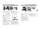
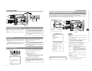
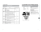
Recording Time Codes in Continuation of Time Codes Recorded on Tape
TC GENE switch
Setting
■Set the TC GENE switch inside the cover on the side to
REGEN.
● The time code framing mode automatically becomes the
mode (drop frame or non drop frame) already recorded on
the tape.
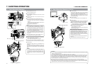
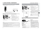
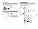
10-4 Reproducing Time Codes
The GY-DV5000 incorporates a time code reader. During playback, the time code or user’s bit data recorded on the tape is displayed
on the LCD monitor or in the viewfinder. (Status screen)
Status screen
Setting
☞ See “Displaying Time Code” on page 62.
CAUTION:
A time code with a duration of more than 2 hours may not
be displayed correctly by DV components for general
consumer use, as some of these lack the capability to
display longer time codes.
00:00:00:00
12
.2V
PLAY 01/02/03 01:23:45
Playback time code indication
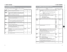
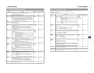
11. MENU SCREENS
65
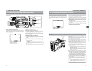
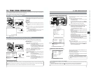
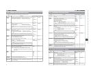
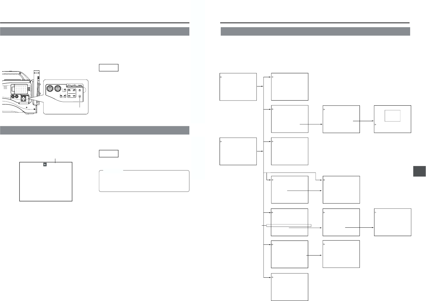
11-1 Menu Screen Configuration
––– MENU –––
CAMERA OPERATION..
CAMERA PROCESS..
AUDIO/VIDEO..
LCD/VF..
TC/UB/CLOCK..
OTHERS..
FILE MANAGE..
MENU ALL RESET CANCEL
EXIT
––– CAMERA OPERATION –––
SHUTTER STEP
FAW NONE
GAIN L 0dB
GAIN M 18dB
GAIN H ALC
LOLUX GAIN 30dB
SMOOTH TRANS ON
SPOT L/BACK L MIDDLE
ASPECT RATIO 4:3
PAGE BACK
––– CAMERA PROCESS –––
MASTER BLACK NORMAL
DETAIL NORMAL
DTL.V/H BALANCE NORMAL
SKIN DTL.DETECT OFF
SCAN
VIDEO
WHITE CLIP 108%
KNEE POINT
100%
ADVANCED PROCESS..
PAGE BACK
––– ADVANCED PROCESS –––
COLOR MATRIX STD
CINE MODE OFF
GAMMA NORMAL
FLARE<R> NORMAL
FLARE<B> NORMAL
SKIN COLOR ADJUST..
PAGE BACK
––– SKIN COLOR ADJUST –––
SKIN COLOR DET. STOP
SKIN COLOR RANGE NORMAL
PAGE BACK
––– MENU –––
AUDIO/VIDEO..
LCD/VF..
TC/UB/CLOCK..
OTHERS..
FILE MANAGE..
MENU ALL RESET CANCEL
EXIT
––– AUDIO/VIDEO –––
TEST TONE OFF
AUDIO MODE 48K
CH1 FRONT VR ENABLE
WIND CUT OFF
AUDIO REF.LEVEL –20dB
AUDIO SELECT CH1/2
AUDIO MONITOR MIX
A.OUT AT SEARCH ON
SET UP 7.5%
PAGE BACK
––– LCD/VF(1/2) –––
ZEBRA 70–80%
F.NO/IRIS IND. OFF
FILTER ON
SAFETY ZONE ON
CENTER MARK OFF
NEXT PAGE
PAGE BACK
––– LCD/VF(2/2) –––
TAPE REMAIN ON
TC/UB ON
AUDIO ON
LCD COLOR NORMAL
LCD PEAKINGS NORMAL
PAGE BACK
––– TC/UB/CLOCK –––
TC PRESET 00:00:00:00
EXECUTE
TC CLEAR CANCEL
UB PRESET 00 00 00 00
EXECUTE
UB CLEAR CANCEL
DROP/NON DROP DROP
TIME/DATE..
PAGE BACK
––– TIME/DATE –––
DISPLAY ON
DISPLAY MODE BARS+CAM
DATE REC OFF
DISPLAY STYLE DATE+TIME
DATE STYLE MM/DD/YY
TIME STYLE 24HOUR
SEC DISPLAY ON
CLOCK ADJUST..
PAGE BACK
––– CLOCK ADJUST –––
DATE(MM/DD/YY) 08/20/02
TIME 09:33
PAGE BACK
––– OTHERS(1/2) –––
OUTPUT CHAR. OFF
NET REMOTE OFF
DV REC TRIGGER OFF
LONG PAUSE TIME 30MIN
REM FF/REW MODE FF/REW
NEXT PAGE
PAGE BACK
––– OTHERS(2/2) –––
ALARM VR LEVEL HIGH
BATTERY TYPE 12V
FRONT TALLY BLINK
BACK TALLY BLINK
PAGE BACK
DRUM HOUR 00200
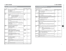
––– FILE MANAGE –––
LOAD FILE CAM1
LOAD CANCEL
STORE FILE CAM1
STORE CANCEL
RESET FILE CAM1
RESET CANCEL
PAGE BACK
STEP SLOW MODE FRAME
TOP MENU screen (CAM)
CLOCK ADJUST screen
TOP MENU screen (VTR)
CAMERA OPERATION screen
CAMERA PROCESS screen
AUDIO/VIDEO screen
LCD/VF screen (1/2)
TC/UB/CLOCK screen
OTHERS screen
FILE MANAGE screen
ADVANCED PROCESS screen SKIN COLOR ADJUST screen
CAM
CAM
CAM
VTR
LCD/VF screen (2/2)
TIME/DATE screen
OTHERS screen
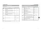
The Menu Screen consists of multiple layers of menu screens as shown below. The menu screen to be set is selected from the TOP
MENU in accordance with the function or purpose.
The items on the menu screens differ with the Camera mode and the VTR mode. The contents of set items are stored in the GY-
DV5000’s memory and are retained even when the power is turned off.
The FILE MANAGE menu screen can be used to store the menu setting contents in two types of files (FILE CAM1, FILE CAM2) on
the GY-DV5000. When saving menu setting contents that remain more or less fixed, these are stored in FILE CAM1 or FILE CAM2.
A saved file (FILE CAM1 or CAM2) can be read out on the FILE MANAGE menu screen.
(U model)