


56
7. SHOOTING OPERATION
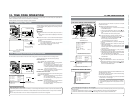
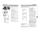
7-5 Recording the Color Bars
MONITOR
EDITSEARCH
FILTER
STATUS
SHUTTER
MENU
AUTO IRIS
BACK L
NORMAL
SPOT L
STRETCH
NORMAL
COMPRESS
FULL AUTO BLACK LOLUX
MODE
POWER
ON OFF
VTR
OPEN
VTR
CAM
1
3200K
5600K
5600K
5600K
ND
/
/
ND
2
.3
.4
1
8
1
64
CH-1
AUDIO INPUT
AUDIO SELECT
CH-2
CH-1 CH-2
FRONT
REAR
AUTO
MANUAL
AUDIO
LEVEL
CH-1 CH-2
PULL
OPEN
LCDBRIGHT DISPLAY
POWER
ON OFF
VTR
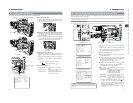
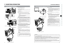
OUTPUT switch
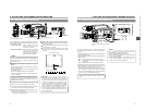
Color bar signal of the built-in signal generator
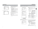
An SMPTE standard color bar is output.
Whether the camera image should be output or whether the
color bar of the built-in signal generator should be output can
be selected during record-standby and recording.
■To output the color bar, set the OUTPUT switch to the
BARS side.
■To output the camera image, set the OUTPUT switch to
the CAM AUTO KNEE ON/OFF side.
MEMO:
Whether or not the audio reference signal should be output
while the color bar is output can be selected with the TEST
TONE item on the AUDIO/VIDEO menu screen.
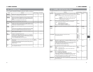
White Yellow Cyan Green Magenta Red Blue
Blue Black Magenta Black Cyan Black White
Black White Black
(E model)
(U model)
An EBU standard colour bar is output.
White
Yellow
Cyan
Green
Magenta
Red
Blue
Black
57
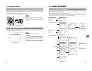
8. PLAYBACK MODE
MEMO:
● The GY-DV5000 can play back the following three types
of videocassettes:
•DV videocassette
• MiniDV videocassette
•DVCAM videocassette
● Tapes recorded in the LP mode cannot be played back.
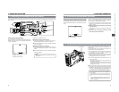
1.
Set the POWER switch to ON.
2.
Set the unit to the VTR mode.
Press the MODE switch upward to turn on the VTR indicator.
● Playback is also possible in the Camera mode.
Playback operation becomes possible when the STOP
button is pressed to set the VTR operation mode indicator
to indicate STOP.
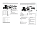
3.
Load the recorded videocassette correctly.
Slide the OPEN knob on the top section of the unit to open
the cassette cover. Then insert the videocassette and close
the cover.
● When the videocassette is loaded, the unit enters the
Stop mode.
4.
Open the operation cover on the upper section of the unit.
Slide the operation cover to the side to open.
5.
Press the PLAY button.
● Playback starts.
6.
Press the STILL button to stop playback temporarily.
● The unit enters the still mode.
7.
To re-start playback, press the PLAY button.
8.
To stop playback or the still mode, press the STOP button.
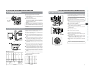
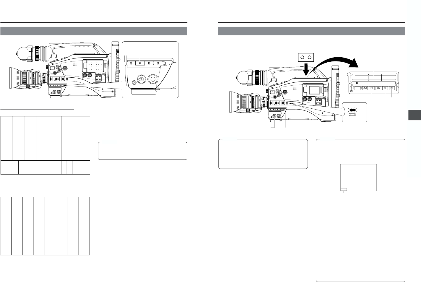
8-1 Playback Procedure
MONITOR
EDITSEARCH
FILTER
STATUS
SHUTTER
MENU
AUTO IRIS
BACK L
NORMAL
SPOT L
STRETCH
NORMAL
COMPRESS
FULL AUTO BLACK LOLUX
MODE
POWER
ON OFF
VTR
OPEN
VTR
CAM
1
3200K
5600K
5600K
5600K
ND
/
/
ND
2
.3
.4
1
8
1
64
CH-1
AUDIO INPUT
AUDIO SELECT
CH-2
CH-1 CH-2
FRONT
REAR
AUTO
MANUAL
AUDIO
LEVEL
CH-1 CH-2
PULL
OPEN
LCDBRIGHT DISPLAY
MODE
VTR
CAM
STILLSTOPREW
BLANK SEARCH
FF PLAY
STOP button
MEMO:
● In the VTR mode, the camera image is not output on the
LCD monitor, in the viewfinder or through the video output
connector.
● The VTR mode is indicated on the LCD monitor and in
the viewfinder. (Status screen)
● When the still picture mode or stop mode has continued
for a while, the unit automatically switches to the tape
protect mode.
Tape protect mode: Drum rotation is stopped in order to
protect the tape.
● Noise may appear in the picture in the still mode.
● When the automatic tracking function is activated at the
start of the playback mode, digital noise may appear in
the playback image.
● This unit does not allow manual tracking adjustment.
● When playing back a tape that was recorded on another
unit, digital noise may appear during playback.
● Following loading of the tape, the built-in head cleaner
will emit a sound while operating. This does not indicate
a malfunction.
● The data recorded for the date and time or time code on
the tape can be shown on the screen. To enable or disable
the display is selected on the menu screen:
Display of date and time:TIME/DATE menu screen
Display of time code: LCD/VF (2/2) menu screen
VTR operation mode indication
TC00:00:00:00
20
min
12
.2V
PLAY 01/02/03
AM
––:––:––
POWER switch
MODE switch
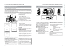
Recorded pictures can be viewed in the viewfinder, or on the LCD monitor, or on the monitor connected to the video output
connector.
Operation cover
Still button
PLAY button