


60
9. USING EXTERNAL COMPONENTS
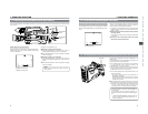
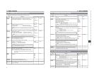
9-1 Connecting a Video Component with DV Connector
PHONES
DC OUT
DC IN
DV REAR AUDIO IN TAL LY
MONITOR
EDITSEARCH
FILTER
STATUS
SHUTTER
MENU
AUTO IRIS
BACK L
NORMAL
SPOT L
STRETCH
NORMAL
COMPRESS
FULL AUTO BLACK LOLUX
MODE
POWER
ON OFF
VTR
OPEN
VTR
CAM
1
3200K
5600K
5600K
5600K
ND
/
/
ND
2
.3
.4
1
8
1
64
CH-1
AUDIO INPUT
AUDIO SELECT
CH-2
CH-1 CH-2
FRONT
REAR
AUTO
MANUAL
AUDIO
LEVEL
CH-1 CH-2
PULL
OPEN
LCDBRIGHT DISPLAY
MODE
VTR
CAM
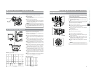
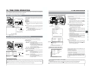
Connecting the GY-DV5000 to another video component equipped with DV I/O connector (IEEE1394 standard) using a DV cable
(optional) enables dubbing of digital signals with high picture quality and high-quality sound.
1.
Connect the units with the DV cable.
2.
Tu rn ON both units.
3.
Place the GY-DV5000 in the VTR MODE.
Press the MODE switch upward to turn on the VTR indicator.
4.
Insert the videocassettes.
GY-DV5000: Insert the recorded videocassette.
Recording unit: Insert the videocassette to be dubbed to.
5.
Press the PLAY button on the GY-DV5000 to start playback.
6.
Start recording on the recording unit.
For details, see the instructions to the unit used for recording.
7.
When dubbing is completed.
Stop recording on the recording unit, and then press the
STOP button on the GY-DV5000 to stop playback.
MEMO:
● The operation methods differ with the characteristics and specifications of the connected equipment. Even if connection is
possible, operation or data communication may sometimes be impossible to perform.
● If block noise appears or the sound falls out, try to disconnect and then connect the DV cable again, or turn the power to the
GY-DV5000 off and then on again.
● When connecting to a D-9 (digital-S) component with an IEEE1394 connection, the date and time data are not output from
the D-9 component. Also, the date and time data cannot be recorded on the D-9 component. When making an IEEE1394
connection with a D-9 component, install SA-DV60 on the device.
● If the power to the component connected to the DV connector is turned on, or the video input is changed, noise may appear
in the audio. When these operations have to be performed, reduce the sound volume of the audio component, speaker, etc.,
connected to the GY-DV5000 to a minimum.
● When using the TC DUPLICATE mode of BR-DV600A, set Menu No. 416 [NON DROP/DROP] of BR-DV600A according to
the framing mode (Drop/Non-drop) of the tape to be played back on this unit.
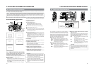
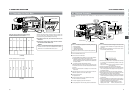
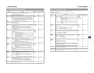
When Using the GY-DV5000 as Playback Unit (Dubbing to Another Video)
MODE switch
● Dubbing still images makes the images coarser. In addition,
noise may appear in the sound.
Video component with DV Connector
DV connector
DV cable (VC-VDV204 (4P-4P), VC-VDV206 (4P-6P))
DV connector
Rear section of GY-DV5000
61
9. USING EXTERNAL COMPONENTS
MONITOR
EDITSEARCH
FILTER
STATUS
SHUTTER
MENU
AUTO IRIS
BACK L
NORMAL
SPOT L
STRETCH
NORMAL
COMPRESS
FULL AUTO BLACK LOLUX
MODE
POWER
ON OFF
VTR
OPEN
VTR
CAM
1
3200K
5600K
5600K
5600K
ND
/
/
ND
2
.3
.4
1
8
1
64
CH-1
AUDIO INPUT
AUDIO SELECT
CH-2
CH-1 CH-2
FRONT
REAR
AUTO
MANUAL
AUDIO
LEVEL
CH-1 CH-2
PULL
OPEN
LCDBRIGHT DISPLAY
MODE
VTR
CAM
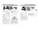
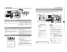
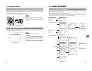
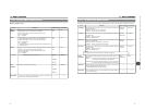
TC00:00:00:00
REC 01/02/03 01:23:45
MODE switch
Date and time data:
Data transmitted from the playback unit is recorded.
Time code:
The data generated by the GY-DV5000’s time code generator
is recorded.
Date and time
Master unit
When Using the GY-DV5000 as RECORDING Unit (Dubbing From Another Videocassette)
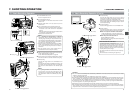
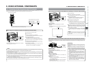
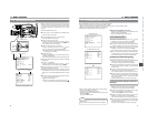
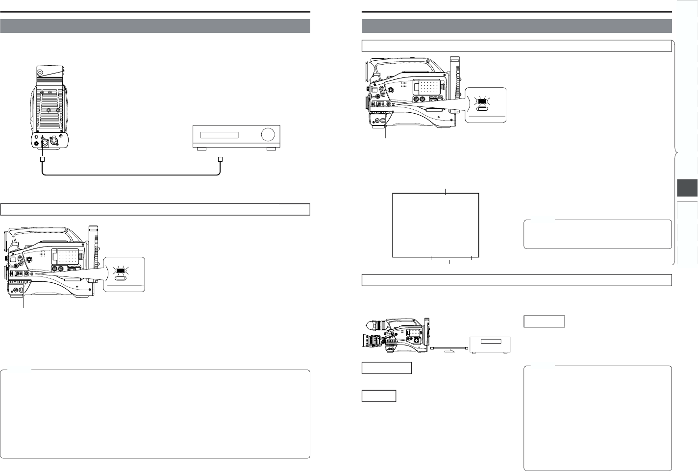
Backup Recording of the GY-DV5000's Camera Image and Sound Through the DV Connector
1.
Tu rn ON both units.
2.
Place the GY-DV5000 in the VTR MODE.
Press the MODE switch upward to turn on the VTR indicator.
3.
Insert the videocassettes.
GY-DV5000: Insert the videocassette to be dubbed to.
Playback unit: Insert the recorded videocassette.
4.
Connect the units with the DV cable.
5.
Start playback on the playback unit.
For details, see the instructions to the unit used for playback.
● The playback picture from the playback unit appears on
the GY-DV5000’s LCD monitor and viewfinder screen.
6.
Press the VTR trigger on the GY-DV5000 to start recording.
■To temporarily pause the recording, press the VTR trigger.
■To restart the recording, press the VTR trigger again.
7.
When dubbing is completed.
Press the VTR trigger or the STOP button on the GY-DV5000
to stop recording, and then stop playback on the playback
unit.
Time code
MONITOR
EDITSEARCH
FILTER
STATUS
SHUTTER
MENU
AUTO
IRIS
BACK L
NORMAL
SPOT L
ST
RETCH
NO
RMAL
CO
MPRESS
FULL AU
TO
BLACK LOLUX
MODE
POWER
O
N
OFF
VTR
O
PEN
VTR
CAM
1
3200K
5600K
5600K
5600K
ND
/
/
ND
2
.3
.4
1
8
1
64
CH-1
AUDI
O INPUT
AUDIO
SELECT
CH-2
CH-1 CH-2
FR
ONT
R
EAR
A
UTO
MA
NUAL
AUDIO
LEVEL
CH-1 CH-2
PUL
L
OP
EN
LCD BRIGHT DISPLA
Y
The GY-DV5000’s camera image and sound can be recorded for backup on another component that is equipped with DV connector.
Recording operation is performed on the backup equipment simultaneously with performance of the recording operations on the
GY-DV5000.
Connections
Use the GY-DV5000 as the master unit.
Connect the master unit and the backup unit with a DV cable
DV cable
Signal flow
Backup unit
Settings
■Master unit (GY-DV5000)
● Place in CAMERA mode.
● Set the DV REC TRIGGER item on the OTHERS (1/2)
Menu Screen to ON.
■Backup unit
● Place in DV signal input mode.
* Depending on the used component, it may be necessary
to set “REMOTE SELECT”.
● When BR-DV600A or BR-DV3000 is used, set the Backup
Recording function to OFF.
● Insert the tape and set to STOP or REC PAUSE status.
Operation
Start and stop of recording on the backup unit takes place in
accordance with the operation of the VTR trigger button on the
master unit.
Start and stop of recording on the backup unit takes place in
accordance with start and stop of recording on the master unit.
MEMO:
● When the backup recording is started, the “TRIGGER
TO DV” indication is shown on the LCD or in the
viewfinder for 3 seconds.
● When the Backup Recording function of BR-DV600A or
BR-DV3000 is used, the DV REC TRIGGER item on the
GY-DV5000’s OTHERS (1/2) Menu Screen should be set
to OFF.
● If the backup device is equipped with a feature to record
time codes input from the DV IN/OUT terminal (TC
DUPLICATE feature), time code data the same as on
the master side can be recorded.
● When using BR-DV600A as a backup device and
switching GY-DV5000 from the EDIT SEARCH or
PLAYBACK mode to the RECORD mode, noise will be
noticed on the monitor output screen of BR-DV600A
(backup will be correctly recorded).
MEMO:
Depending on the player, sound may not be heard
momentarily from this unit when switching modes from
STILL to PLAY.
(U model)