


10 EN
Connections & Installation (continued)
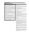
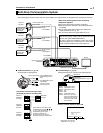
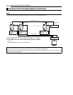
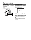
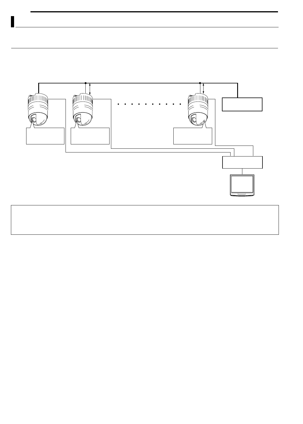
A system that does not employ the RM-P2580 as the controller.
MEMO
●Be sure to terminate the control signal cable at both ends. The cables (length of stub) connecting pieces of non-terminated equipment (cameras
or controllers) must be as short as possible. If the length of stub is too long, control precision may suffer.
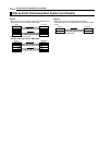
Multi-Drop Communication System (continued)
CAUTIONS
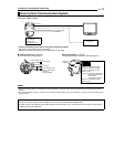
●The AC 24 V power supply must be isolated from the primary line. (ISOLATED POWER ONLY)
●In order to prevent an excessive current flow through the power supply wire or camera due to a short circuit, a fuse must be
installed in the power supply line.
PROTOCOL(1) : ON
MACHINE ID : 01
RX TERM : ON
PROTOCOL(1) : ON
MACHINE ID : 02
RX TERM : OFF
PROTOCOL(1) : ON
MACHINE ID : 32
RX TERM : OFF
CONTROLLER*
CAM1 CAM2 CAM32Length of stub
CONTROL Cable
Length of stub Terminate it with
110
K
.
VIDEO
SWITCHER, etc.
●An AC 24V power source must be supplied to each camera. (A CAUTIONS)
●Set the TERM switch of the camera connected lastly (CAM1 in the example
of the above figure) to ON, and terminate at the controller with a resistance
of 110 K.
Set the TERM switches of the other cameras to OFF.
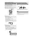
Coaxial Cable