


18 EN
Connections & Installation (continued)
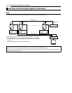
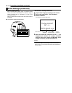
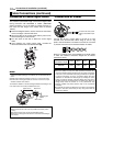
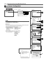
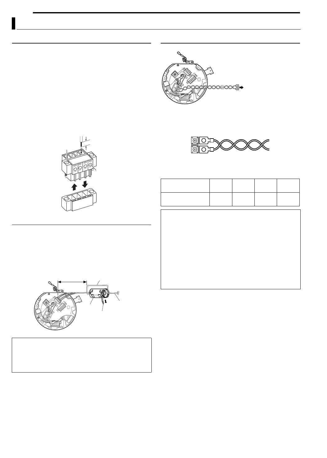
Connection of Control Signal Cables
Connect this to the remote control unit (RM-P2580).
The maximum permissible length of the control signal cable
during connection with RM-P2580 is 1200m. (RM-P2580
allows connection of a set of cables to multiple cameras. In
this case, the total length of the cables shall not exceed
1200m.)
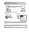
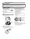
A Follow the diagram below to loosen and remove the screws
on the two edges of the terminal block.
B Strip the coating of the control signal cable by about 4 mm
before inserting it into the terminal.
C Turn the screw on the side to fasten the control signal
cable.
D Upon fastening the control signal cable, re-install the
terminal block that has been dismantled in
A.
MEMO
●Instead of using 0.65, 4-core cables (2 pairs), it is recommended that
twisted pair cables (category 3 and above) for use with Ethernet be
used.
●Cables with a thickness between 0.4 mm to 1.3 mm can be used.
●Connect the control signal cables so that TX+ and TX- form a pair
and RX+ and RX- form another.
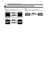
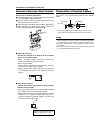
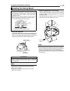
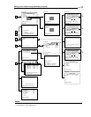
To reduce the radiation of the Control Signal Cables connecting to this
unit, make sure to mount the provided Ferrite Core.
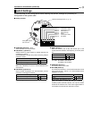
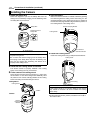
Connection of Power
Connect to an AC 24 V Supply.
Connect the AC 24 V power cable to the AC 24 V input
terminal of the terminal block. When doing so, use of a lug
plate is recommended for connection to the AC 24 V terminal
to prevent connection errors and disconnection of cables.
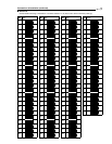
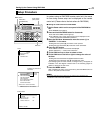
When a 2-conductor VVF (vinyl-insulated vinyl sheath cable)
is used, the maximum connection lengths are as follows.
(Reference values)
Cable Connections (continued)
CAUTIONS
●Mount the Ferrite Core as close as possible the camera (within
10 cm).
●Secure the Ferrite Core with the provided Wire Clamp.
●Pass the wire through the Ferrite Core once before connecting to
the camera.
4mm
A
C
B
Cable
A
D
Within 10 cm
Wind once
Wire Clamp
Ferrite
Core
Control Signal
Cables
Ceiling Mount
Maximum
Connection Length
100 m 260 m 410 m 500 m
Conductor
Diameter
R
1.2 or
more
R
1.8 or
more
R
2.3 or
more
R
2.9 or
more
CAUTIONS
●When thin cables are used, the cable resistance increases. As a
result, the effective voltage will drop when the power consumption
of the unit is at its maximum level (during simultaneous operation
of panning and tilting). As such, use thicker cables with lower
resistance, or decrease the cable length by installing the power
supply unit near the camera, such that voltage drop upon flow of
the rated current of the camera does not exceed 10%. When the
voltage drops while the camera is in use, performance may
become unstable and preset positions may not be reproduced
accurately.
●The internal circuit may be damaged if the cable is connected by
mistake. In this case, ensure that you stop using and contact the
nearest JVC dealers.
Power Cable
Connect to AC 24 V power
supply. Listed class 2 input
only.