


EN 11
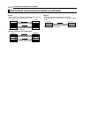
Connections & Installation (continued)
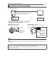
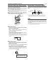
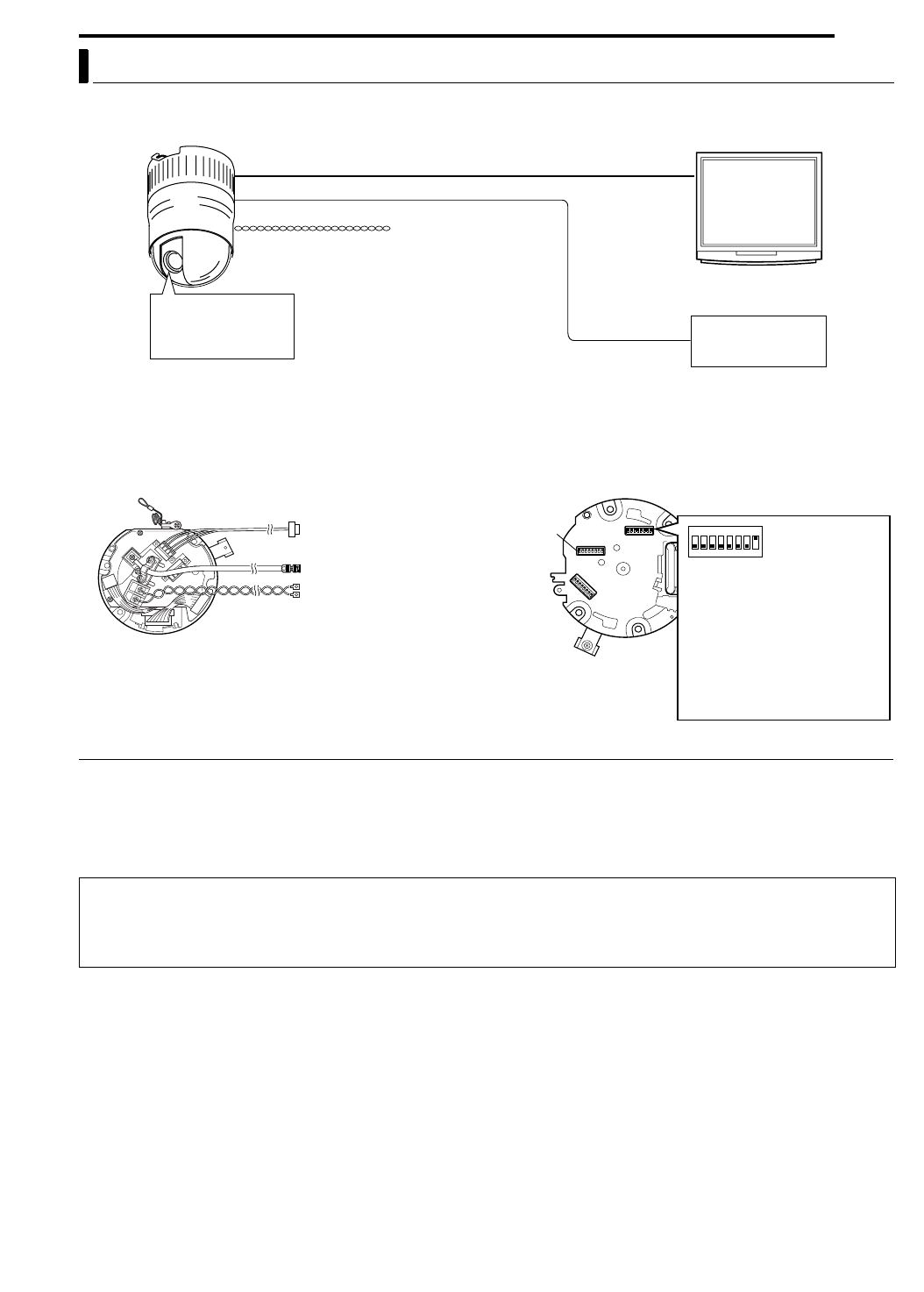
The following illustration shows a system in which a remote control unit (or a similar piece of equipment)
controls a single camera.
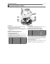
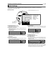
8 ACable ConnectionsB (A pg. 16)
(Terminal side of the Ceiling Mount)
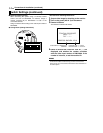
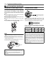
8 ASwitch SettingsB (A pg. 13)
(Setting switches are on the side of the Ceiling Mount)
MEMO
●If this camera or the cables connected to this camera are used in places subject to strong electromagnetic waves or other forms of magnetism,
such as those near a radio or TV transmitter, a power transformer or an electric motor, the picture may suffer from noise and colors may be
affected.
●An optionally available controller is required to use a TK-C625 camera. Please contact your local dealer or installer for more information about
these controllers.
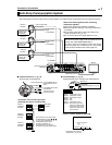
Point-to-Point Communication System
Controller
Control signal cable
Video out
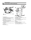
Observe the following points when connecting components together:
●Turn all the components off before proceeding.
●Read the instruction manuals of all components before proceeding.
Switch 4 : OFF
(Point to Point)
Switch 8 : ON
(Terminated 110 K)
AC 24 V power supply
(A CAUTIONS)
Monitor
Control signal cable
Coaxial cable
Power cable
To controller
To monitor
To the AC 24V power
supply. Listed class 2
input only.
(A CAUTIONS)
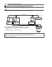
Setting not
required
Switch 1 : Invalid (Set to OFF)
Switch 2 : Invalid (Set to OFF)
Switch 3 : Invalid (Set to OFF)
Switch 4 : OFF
Switch 5 : Configure in accordance
with the requirements of
the controller
communication system.
Switch 7 : Invalid (Set to OFF)
Switch 8 : ON
CAUTIONS
●The AC 24 V power supply must be isolated from the primary line. (ISOLATED POWER ONLY)
●In order to prevent an excessive current flow through the power supply wire or camera due to a short circuit, a fuse must be
installed in the power supply line.