


EN 43
Other (continued)
Specifications
8 Camera
Image pickup device:1/4 type, interline transfer CCD
TK-C625E: 752 (H) x 582 (V) pixels
TK-C625U: 768 (H) x 494 (V) pixels
Sync system : Internal, Line Lock
Video output : VBS 1V (p-p) 75 K
Scanning frequencies
:TK-C625E: 15.625 (H), 50 Hz (V)
TK-C625U: 15.734 (H), 59.94 Hz (V)
S/N: 50 dB (typical) (AGC mode: OFF, Enhance
level:
-
5)
Horizontal resolution
: 540 lines and above (typical) (WIDE end,
Centre)
Minimum object illumination
:
Color mode :
3.6 lx (50 % output, AGC 20 dB, WIDE end)
1.8 lx (25 % output, AGC 20 dB, WIDE end)
B&W mode : 0.15 lx (50 % output, AGC 20 dB, WIDE
end)
White balance : TTL auto tracking/Manual
Electronic shutter
:
TK-C625E : 1/50 (standard), 1/120 (60 Hz flickerless),
1/250, 1/500, 1/1000, 1/2000, 1/4000,
1/10000
TK-C625U : 1/60 (standard), 1/100 (50 Hz flickerless),
1/250, 1/500, 1/1000, 1/2000, 1/4000,
1/10000
Backlight compensation: Possible, 4 photometry areas selectable
Color level adjustment: Possible
Contour correction: Both horizontal and vertical (level adjustable)
8 Lens
Zoom ratio : Approx. x12
Focal distance : 3.8 mm to 45.6 mm
Maximum aperture : F1.6 (WIDE) to F2.7 (TELE)
8 Pan/Tilt Mechanism
Panning range : 360° endless revolution
Panning speed : 1.5°/s to 180°/s
Tilting range : 0° to 90° (Horizontal - Straight
downwards - Horizontal)
Tilting speed : 1°/s to 120°/s
8 General
Power supply : TK-C625E: AC 24 V, 50 Hz, 1.5 A
TK-C625U: AC 24 V, 60 Hz, 20 W
No. of preset positions
: 100
Applicable control unit
:RM-P2580
Ambient temperature
:-10I to 50I (operating),
0I to 40I (recommended)
Ambient humidity :
35 % to 90 % RH
(without condensation)
Mass : 1.3 kg
Accessories:
TK-C625E : Instructions ...................................... 2
Ceiling Mount................................... 1
Te mplate.......................................... 1
Wire Clamp...................................... 1
TK-C625U : Instructions ...................................... 1
Warranty Card.................................. 1
Service Information Card................. 1
Ceiling Mount................................... 1
Te mplate.......................................... 1
Ferrite Core...................................... 1
Wire Clamp...................................... 1
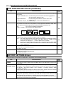
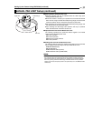
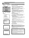
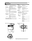
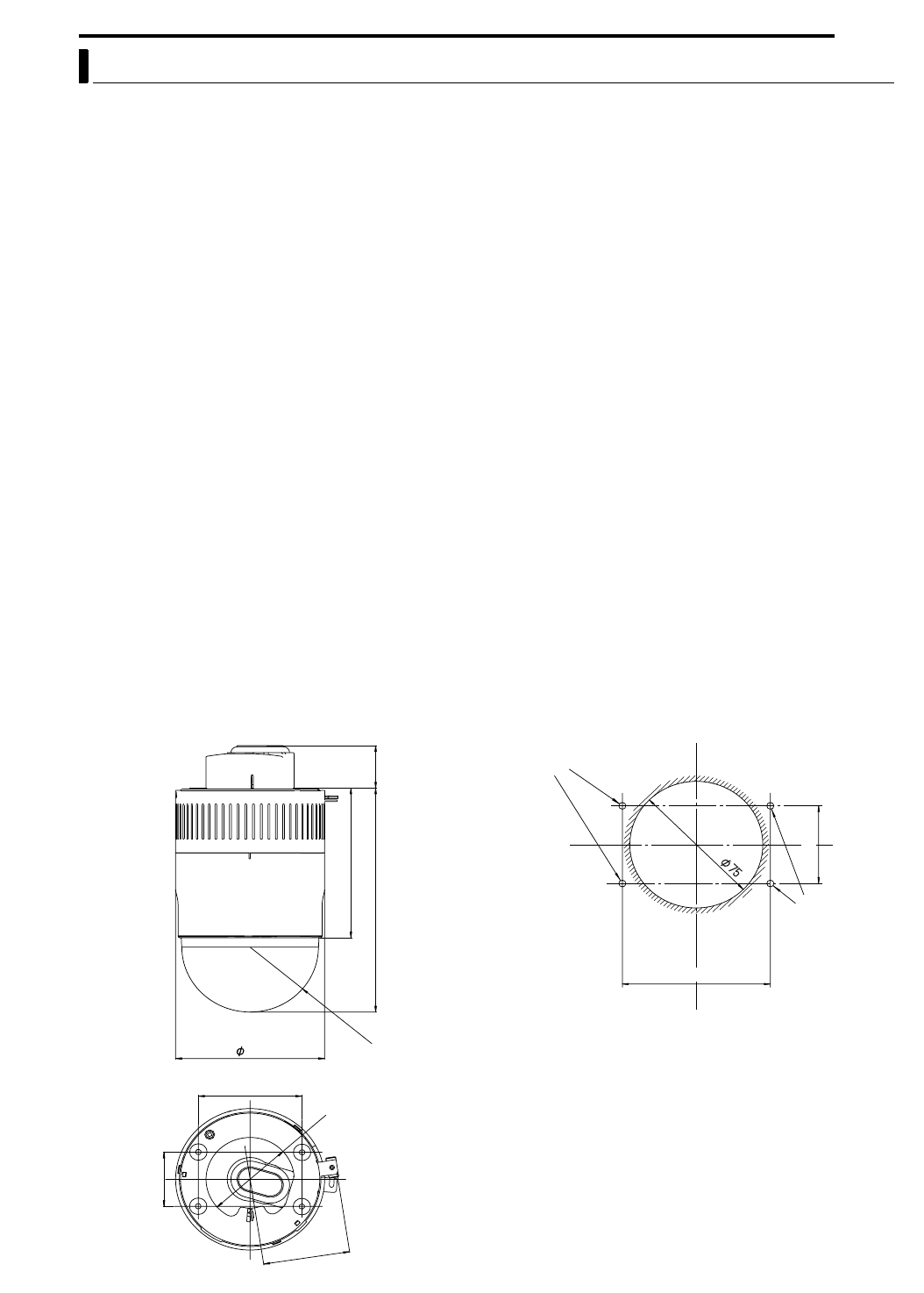
70
190 36
127
83.5
120
46
SR55
7
1
46
83.5
Mounting hole
●Specifications and appearance of this unit and related products are
subject to change for product improvement without prior notice.
8 External Dimensions [Unit: mm] 8 Ceiling Mount Hole [Unit: mm]
Screw
Positions
Screw
Positions