


EN 9
Connections & Installation
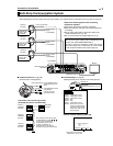
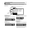
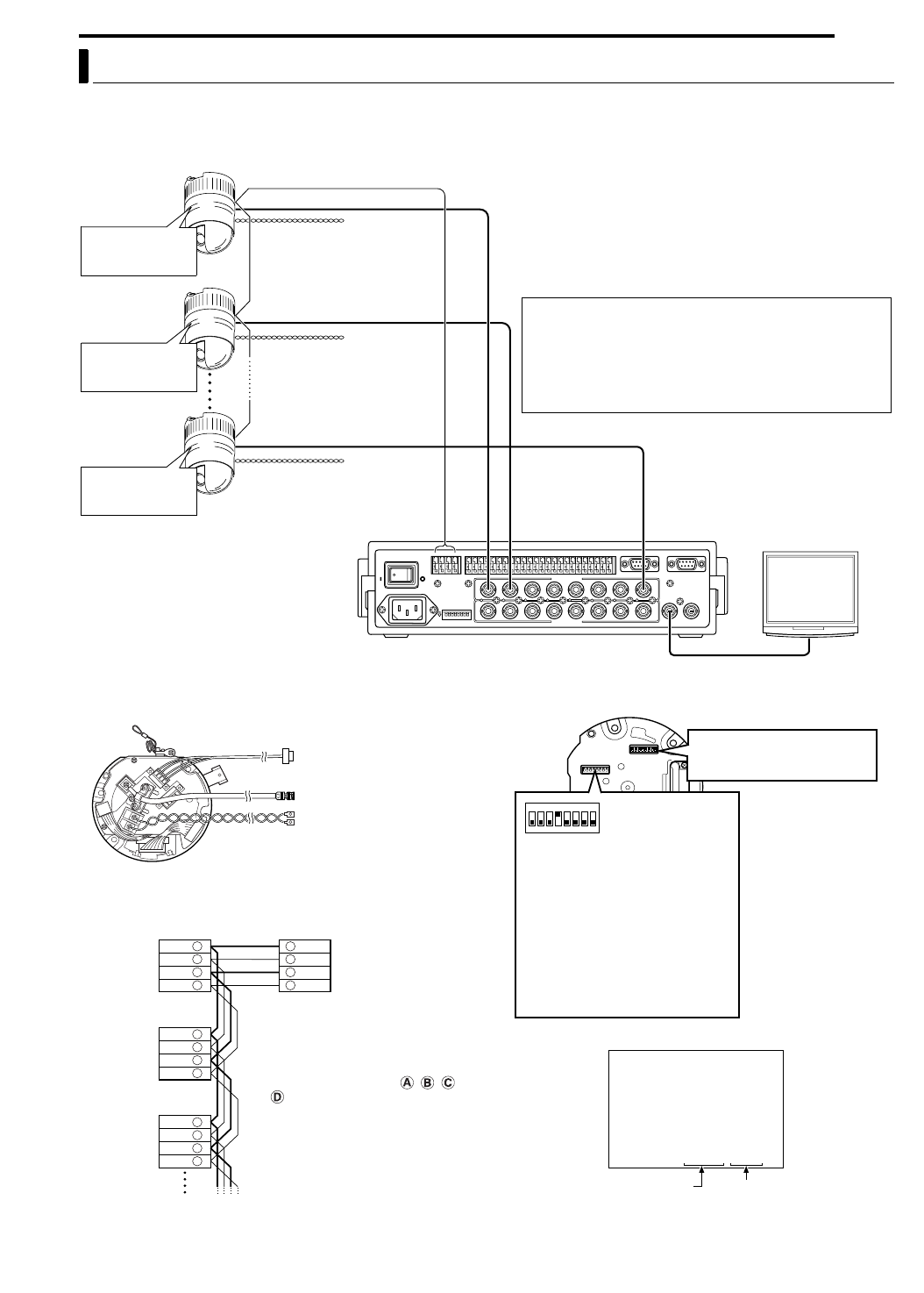
A system that employs the RM-P2580 as the controller.
The following figure shows a system that can accommodate up to eight cameras. (100 positions can be preset per camera.)
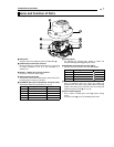
8 ACable ConnectionsB (A pg. 16)
(Terminal side of Ceiling Mount)
8 ASwitch SettingsB (A pg. 13)
(Setting switches are on the side of the Ceiling Mount)
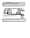
Multi-Drop Communication System
1
TOCAMERA DATAI/O
RX
+
RX
-
TX
+
TX
-
COM
1 2 3 4 5 6 7 8
COM
9/110/211/312/413/514/615/716/8
COM COM COM
CAMERA
SW
UNIT
ALARM
AUTO
4312 8756
2 3 4 5 6 7
8
1
MONITOR
OUTPUT
MONITOR
SERIAL-2SERIAL-1
VIDEOINPUT
VIDEOOUTPUT
OUTPUT
2
1
ON
2 3 4 5 6 7
8
POWER
OFF
ON
AC INPUT
Observe the following points when connecting
components together:
●Turn all the components off before proceeding.
●Read the instruction manuals of all components before
proceeding.
●For the types and lengths of connection cables, see
ACable ConnectionsB (A pg. 16).
●Do not connect the control signal cables in a loop.
CAUTIONS
●The AC 24 V power supply must be isolated from the
primary line. (ISOLATED POWER ONLY)
●In order to prevent an excessive current flow through
the power supply wire or camera due to a short circuit,
a fuse must be installed in the power supply line.
Camera 1
MACHINE ID: 01
Switch 8: OFF
(RX TERM)
Control signal cable
Remote control unit
RM-P2580
Monitor
Coaxial cable
AC 24 V power
supply
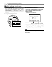
A CAUTIONS
TO CAMERA
MONITOR OUTPUT 1
MACHINE ID: 02
Switch 8: OFF
(RX TERM)
MACHINE ID: 08
Switch 8: ON
(RX TERM)
AC 24 V power
supply
A CAUTIONS
AC 24 V power
supply
A CAUTIONS
TK-C625
Camera 2
TK-C625
Camera 8
TK-C625
TX +
TX -
RX +
RX -
TX +
RX +
RX -
TX +
TX -
TX -
RX +
RX -
TX +
TX -
RX +
RX -
A
B
C
D
A
B
C
D
A
B
C
D
A
B
C
D
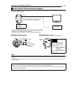
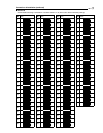
Each terminal on the camera and
the RM-P2580 is marked , , ,
or . In order to facilitate
understanding and to avoid
connection mistakes, it is
recommended to connect the
terminals carrying the same marks.
Control signal cable
Coaxial cable
Power cable
To the TO CAMERA terminal of
the RM-P2580 and to the next
camera
To the CAMERA INPUT terminal
of the RM-P2580
To AC 24V power supply
Listed class 2 input only
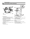
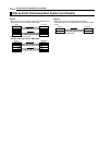
Connection of the control signal cable
(A twisted pair cable is recommended.)
Camera 1
CONTROL
terminals
Camera 2
CONTROL
terminals
Camera 3
CONTROL
terminals
RM-P2580
terminals
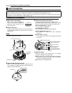
<<>>
:--I--PAN
:--I--TILT
DUPLEX ID-01
INITIAL PROCESS
PROTOCOL
Set to the Video Input number of
RM-P2580.
(Setting procedures A pg. 14)
Switch 1 : Invalid (Set to OFF)
Switch 2 : Invalid (Set to OFF)
Switch 3 : Invalid (Set to OFF)
Switch 4 : ON
Switch 5 : OFF
Switch 7 : Invalid (Set to OFF)
Switch 8 : Set to ON only for the
camera connected at the
end of the control signal
cable. Set to OFF for all
other cameras.
Camera 1 monitor display at power ON
Duplex display
A<Procedures for Checking
Machine ID>B (A pg. 14)
ID No. display
Machine ID