


Introduction (continued)
EN 7
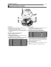
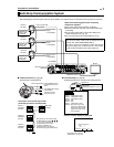
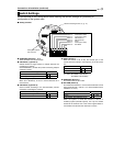
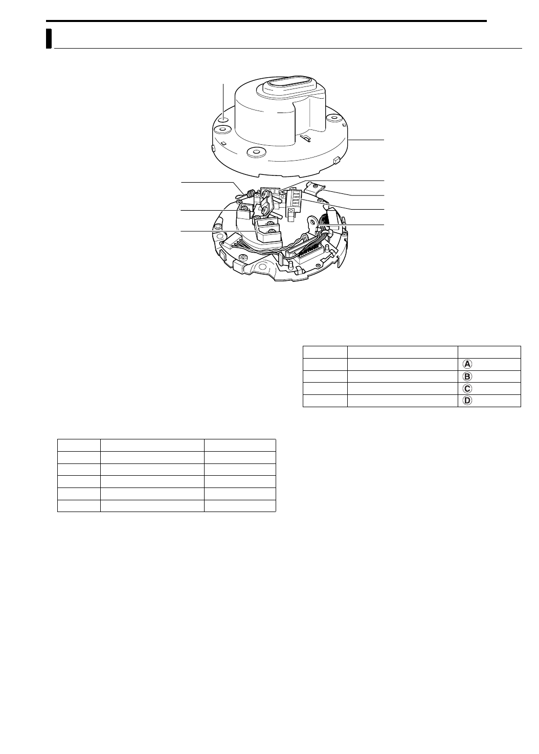
8 Ceiling Mount (Terminal Side)
A Safety Wire
Hang this wire to the Fastening Hook for Safety Wire
S.
B [VIDEO OUT] Coaxial Cable Terminal
Output terminal of a composite video signal (1 V(p-p)) with
an output impedance of 75 K, to be connected to a
switcher, etc.
C [AC24V H INPUT] AC 24 V Input Terminal
Connect to a AC 24 V power supply.
D Safety Wire Mounting Hole
To prevent the camera from falling down, pass the wire from
the ceiling slab or channel to this hole.
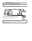
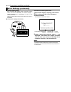
E [ALARM IN / OUT] Alarm Input/Output Terminals (J502)
Terminals for alarm input and output. (A pg. 17)
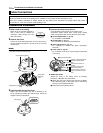
F Locking Screw
For fastening the camera body. Ensure to fasten the
Camera Clamping Bracket
P using this screw.
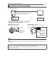
G [CONTROL] Control Signal Terminal (J501)
Connect this to the remote control unit (RM-P2580).
H Cover
This is a protection cover. Cut a slit in the rubber cap
attached to the cover when wiring cables. When connecting
cables to the ceiling mount, ensure to do so by running the
cables through the Cover
H. (A pg. 16)
I Cover Fastening Screw
This is used for fastening the Cover
H and the ceiling
mount.
To remove Cover H, do so by unfastening this screw.
Name and Function of Parts
A
B
C
I
H
G
F
E
D
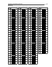
Pin No. Signal Name Displayed As
1Alarm Output + OUT +
2Alarm Output - OUT -
3Alarm Input IN
4GND GND
5 ^ RESERVED
Pin No. Signal Name Displayed As
1TX +
2TX -
3RX +
4RX -