


14 EN
Connections & Installation (continued)
Switch Settings (continued)
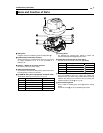
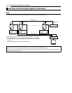
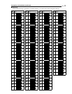
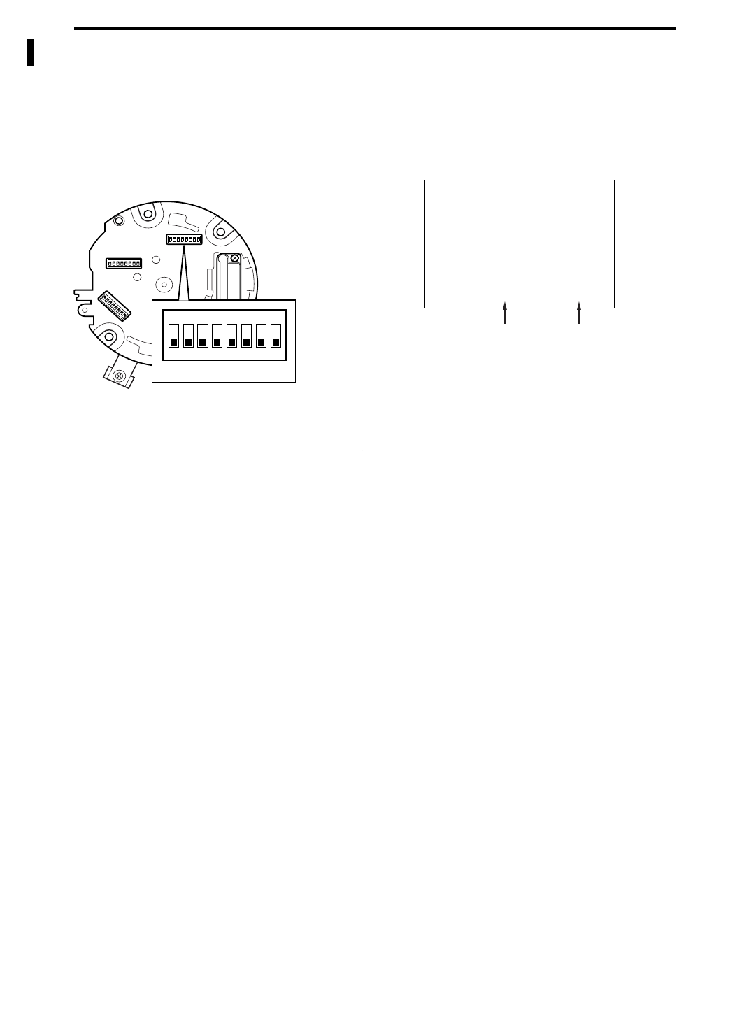
8 Machine ID Setting Switch
When controlling the system using a multi-drop remote
control unit such as RM-P2580, for instance, assign a
number (machine ID) for identification to each of the
connected cameras.
Assign a machine ID according to the video input number of
RM-P2580.
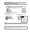
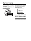
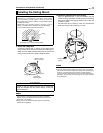
R Ceiling Mount (Setting Switch Side)
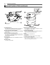
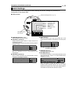
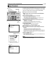
<Procedures for Checking Machine ID>
1 Output video image for checking to the monitor
2 Turn on the power (AC 24 V) of the camera
3 Camera initializes
The following message will appear.
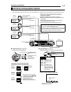
4 Check to ensure that “DUPLEX” and AID-LLB are
displayed, and whether the number coincides
with the video input number of RM-P2580. If the
number is incorrect, re-set the machine ID.
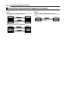
MEMO
●For systems using RM-P2580, a set of control signal cables are
connected to multiple cameras during use. Errors in the switch
setting of any one of the cameras will therefore cause malfunction in
the entire system.
Machine ID
>>
INITIAL PROCESS
<<
PAN:--I--
TILT:--I--
PROTCOL DUPLEX : ID-01
Check that this is displayed as
“DUPLEX”
Displayed as ID-LL. Check
that the number LL is correct.