


16 EN
Connections & Installation (continued)
Connection Procedure
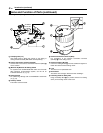
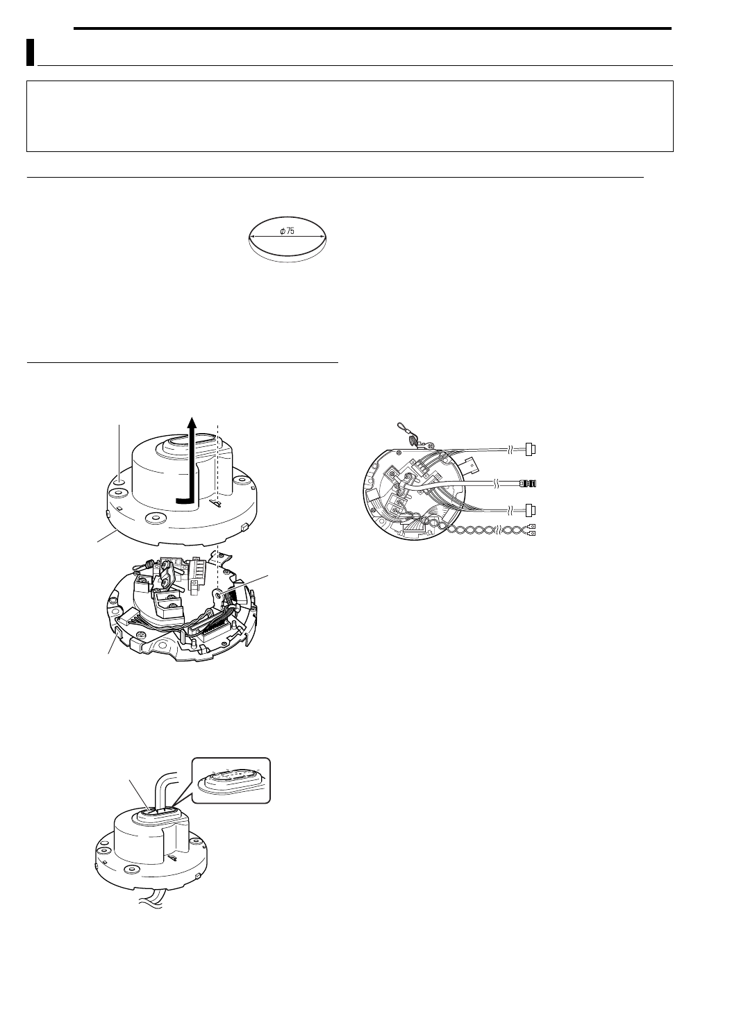
1 Make a hole in the ceiling
Make use of the template supplied to
open a hole (R75) for leading the
connection cable through the rear
side of the ceiling.
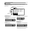
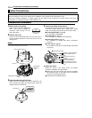
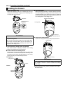
2 Remove the Cover
Loosen the Cover Fastening Screw, and turn the Cover in
the anti-clockwise direction to remove the Cover from the
ceiling mount.
MEMO
●When loosening the Cover Fastening Screw, do so while ensuring
that it does not protrude from the hole.
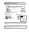
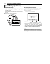
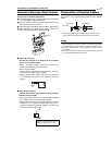
3 Lead the cable through the Cover
Make a slit on the (rubber) cap that is attached to the
Cover, followed by leading the cable through. Follow the
diagram below to make the slit.
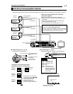
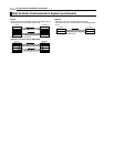
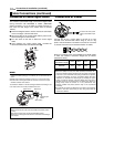
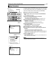
4 Connect the cable to this camera
Connect cables to the terminal on the ceiling mount.
Connection cables include alarm signal cable, coaxial
cable, control signal cable and the AC 24 V power cable.
A Control Signal Cable (A pg. 18)
For connection to RM-P2580.
B Coaxial cable (A pg. 17)
For connection of monitors and other devices.
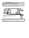
C Alarm signal cable (A pg. 17)
For connection to devices with alarm input/output
terminals.
D Power cable (A pg. 18)
For connection to an AC 24 V power supply. Listed class
2 input only.
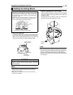
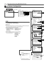
5 Attach the Cover
Attach the Cover to the ceiling mount by following
procedure of Step 2 in the reverse order.
A Attach the cover upon aligning the hole with the Safety
Wire Mounting Hole on the ceiling mount, followed by
turning it in the clockwise direction.
B Fasten the Cover Fastening Screw.
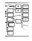
Cable Connections
CAUTIONS
●Ensure to attach the cover for the ceiling mount. Installation is not possible without attaching the cover.
●The cover prevents penetration of foreign objects into the ceiling mount. Penetration of foreign objects may cause a
malfunction or, in the worst scenario, cause smoking or fire.
Cover Fastening Screw
Cover
Safety Wire
Mounting
Hole
Ceiling Mount (Terminal
Side)
Cap (Upper)
A Control Signal Cable
B Coaxial Cable
C Alarm Signal Cable
D Power Cable
Connect to "To Camera" terminal of RM-
P2580 and to subsequent cameras.
Connect to the monitor, etc.
Connect to devices with
alarm input terminal.
Connect to AC 24 V power
supply. Listed class 2 input
only.