


Introduction (continued)
8 EN
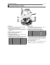
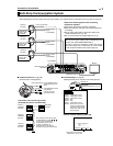
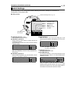
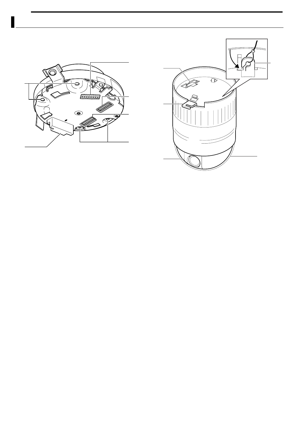
8 Ceiling Mount (Setting Switch Side)
J Clamping Hole (x 4)
Use these holes to attach the camera to the ceiling or
ceiling recessed bracket (WB-S625: sold separately).
K Camera Connection Terminal (Female)
Connect this to the Camera Connection Terminal (Male)
O
on the camera.
L [Machine ID] Machine ID Setting Switch
For systems such as RM-P2580 that make use of the RS-
485 multi-drop communication system, set the ID for
individual cameras. (A pg. 14)
M Setting Switch
For performing settings such as PROTOCOL and SYNC.
(A pg. 13)
N Auxiliary Switch
This switch cannot be used.
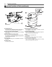
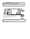
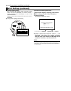
8 Camera
O Camera Connection Terminal (Male)
For connection to the Camera Connection Terminal
(Female)
K on the ceiling mount.
P Camera Clamping Bracket
Insert the Locking Screw
F into this bracket and tighten to
fasten the camera and the ceiling mount.
Q Lens
The lens is not a replaceable item.
R Dome Cover
The dome cover is fragile. Take care when handling it.
S Fastening Hook for Safety Wire
Hang the Safety Wire
A (to prevent camera from falling
down) on the ceiling mount to this hook.
Name and Function of Parts (continued)
FR
ONT
J
J
K
L
M
N
Q
P
O
S
R