


26 EN
Setting Up the Camera Using RM-P2580 (continued)
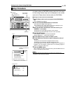
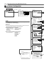
CAMERA TITLE/ALARM Screen
Item Function/Set Value Initial
Value
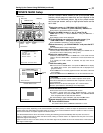
CAM. TITLE EDIT.. Use this to specify the title that is always displayed at the bottom left of the screen. Specify
up to a maximum of 16 characters. ACAMERA TITLE SetupB (A pg. 34)
^
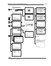
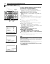
AREA DISPLAY Use this to perform area setting.
AAREA DISPLAY Setup (TITLE)B (A pg. 35)
AAREA DISPLAY Setup (DIRECTION)B (A pg. 36)
OFF
OFF Not displayed.
^
TITLE Equally divides the 360° panning range into 16 areas, and a title of up to 16 characters can
be specified for each area. The corresponding area title specified will be displayed upon
panning the camera manually. AAREA DISPLAY Setup (TITLE)B (A pg. 35)
DIR
Set N (North), which is the direction of the standard axis. When the camera is panned manually,
the 360° panning range will be equally divided into 8 areas, each indicated by N, NE, E, SE, S,
SW, W and NW respectively.
A
AREA DISPLAY Setup (DIRECTION)
B
(
A
pg. 36)
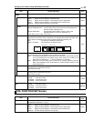
ALARM TITLE SIZE Use this to set the size of the title during an alarm.
NORMAL: Same size as characters on the menu screen.
DOUBLE: Double the size, both vertically and horizontally, of the characters on the menu screen.
DOUBLE
ALARM TITLE
EDIT..
This is a screen for setting the title during an alarm.
AALARM TITLE SetupB (A pg. 37)
^
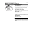
ALARM INPUT.. These items are used to perform setting related to the alarm input terminals.
MODE
For selecting the mode of the camera for which images are to be output when there is an alarm input.
OFF : Does not output images even when there is an alarm input.
HOME : Output images at the home position during an alarm input.
POS1-99 : Output images at a selected preset position during an alarm input.
MEMO
●Setting the AB&W MODEB (A pg. 27) item to AALARM INB switches the mode to the B&W mode and
setting cannot be changed.
OFF
POLARITY For setting the polarity of alarm input signals.
MAKE : Input alarm signals when the contact between each alarm input terminal and the
GND terminal changes from open to closed.
BREAK : Input alarm signals when the contact between each alarm input terminal and the
GND terminal changes from closed to open.
MEMO
●This item will be displayed as "- - -" when the AMODEB item is set to AOFFB and setting is not possible.
MAKE
TIME Use this to set the duration of alarm signal output as well as alarm title display when there is
an alarm.
[Set values: 5 s, 6 s, 7 s, 8 s, 9 s, 10 s, 15 s, 20 s, 30 s, 60 s]
8 CAUTION
For RM-P2580 systems, this setting is disabled. Set using the Alarm Time item of RM-
P2580. (A RM-P2580 AINSTRUCTIONSB)
MEMO
●This item will be displayed as "- - -" when the AMODEB item is set to AOFFB or when the AB&W MODEB
(A pg. 27) item is set to AALARM INB. In both cases, setting will not be possible.
5 s
PRIORITY Sets whether or not manual operation is accepted in case an alarm input is recognized
during manual operation of the camera.
ALARM : Manual operation is not accepted when there is an alarm input.
(Priority given to alarm)
MANUAL : Manual operation is accepted even when there is an alarm input.
(Priority given to manual)
8 CAUTION
This item is invalid with a system using the RM-P2580. With this system, the ALARM
input will permanently override manual operation.
ALARM
ALARM OUTPUT.. Use this to perform setting related to the alarm output terminal.
OFF : Do not output alarm.
ALARM : Output alarm signals when there is an alarm input.
B&W : Output alarm signals when the camera switches to the B&W mode.
PRESET : Output alarm signals when the camera moves to a preset position.
AUX 1 to AUX 3
:Output alarm signals when there is an auxiliary input.
OFF