


18
Preparation (Step 1 Connection/Installation)
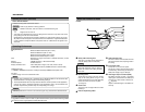
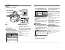
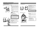
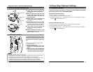
Connect the alarm input/output terminals to
external devices such as sensors and buzzers.
1
Loosen the screws on both edges of the
terminal block using a flathead screwdriver,
followed by dismantling it as shown in the left
diagram.
2
Strip the coating of the alarm signal cable by
about 4mm (1/8 inches) before inserting it into
the terminal.
3
Tu rnthe screw on the side to fasten the alarm
signal cable.
* Connect the alarm terminal according to
step 4 of “2 Installation.” (
☞
Page 20)
1-2 Mounting the Camera to the Ceiling (Continued)
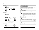
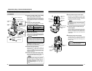
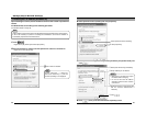
Connect this terminal to an infrared, door or
metallic sensor, or to a manual switch.
Input Requirements
● No-voltage relay or NPN open collector input
● The polarity of input detection can be selected
via software
● Make/Break/Toggle (at least 250 ms)
● Circuit current at low-level: 1.2 mA
● Voltage applied at high level: 12 V
● Alarm Input Terminal
OUT
R
DC12V
GND
1.2mA
R
VCC
OUT
GND
12V
VN-C205
(Alarm Input
Equivalent Circuit)
Grounding
Ter minal
Sensor
Connection
Example (1)
Relay, switch,
etc.
Sensor
Connection
Example (2)
Note
Cable Specifications
50 m or shorter in length
UL1007, UL1015 or equivalent
AWG#22 to AWG#18 or equivalent
Caution
Due to external noise, the cable may not
function properly even when the cable length
is less than 50 m. In this case, use a shielded
cable or take measures such as keeping the
cable away from the noise source.
Alarm Signal
Cable
Flathead
Screwdriver
Flathead
Screwdriver
4 mm (1/8 inches)
1
2
3
1
Ⅵ Connection to Alarm Input/Output Terminal
1. Preparations (Continued)
19
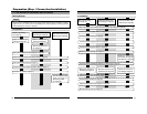
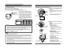
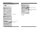
● Alarm Output Terminal
Connect this terminal to alarm devices such
as an annunciator, indicator, lamp or buzzer.
Output Requirements
• Equivalent to NPN open collector output (Set
output logic using the controller)
• Allowed applied voltage: DC12V and below
• Allowed input current: 50 mA
• Momentary output: 1 to 5000ms (Set duration
using the controller)
IN
R
DC 12 V
GND
VN-C205
OUT
Ter minal
Alarm Device
Connection
Example
(Alarm Output
Equivalent Circuit)
Grounding
Ter minal
Caution
Connect the grounding terminal of VN-C205
to the GND terminal of the alarm device.
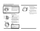
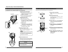
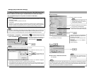
Ⅵ Inserting the CF card
Eject Button
Back
Insert CF card in the direction as indicated
in the diagram
• Press once if the eject button is protruding
• Insert the CF card all the way until you hear a
"click" sound
* When removing the card, ensure that the power
of the camera is turned off before pressing the
eject button.
<List of Tested CF Cards>
• San Disk (Industrial)
128MB (SDCFBI-128-201-80)
256MB (SDCFBI-256-201-80)
512MB (SDCFBI-512-201-80)
1024MB (SDCFBI-1024-201-80)