


10
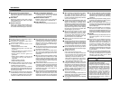
Name and Function of Parts (Continued)
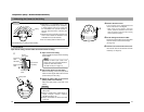
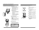
Body Surface
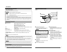
View when the dome cover is removed.
For instructions on removing the dome cover, see step 4 of “Mounting the Camera to the Ceiling”.
(
☞
page 17)
Introduction
8
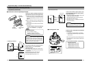
Head
For adjusting the lens, focus, or camera angle.
(
☞
page 23 to 24)
9
Tilt lock screws
Use when adjusting the angle of view of the
camera. (
☞
Page 23)
0
[IRIS LEVEL] Iris level adjustment
For adjusting the level of the automatic aper-
ture control lens. This adjustment only needs
to be made when required. Use this to accom-
modate particular shooting conditions.
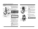
!
MONITOR terminal (RCA pin)
For connecting a monitor when mounting the
camera for adjusting the lens or determining
the camera angle. (High impedance)
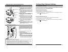
@
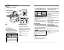
Wire clamp
When pulling out the cables from the side of
camera unit without opening a hole on the
ceiling, arrange the all the cables by bundling
them into this wire clamp.
#
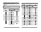
[ALARM IN/OUT] Alarm Input/Output
Terminals
Ter minals for alarm input and output.
(
☞
Page 18)
$
CF card Slot
Insert the CF card. (
☞
Page 19)
&
^
)
¤
fi
(
*
9
8
!
# $ %
0
@
⁄
‹
›
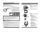
Video setting switch
Turning direction of level
To darken image Counterclockwise (L side)
To brighten image Clockwise (H side)
Note
● When adjusting the iris level, set the
AGC switch to “OFF”. Otherwise, when
the level is turned too far toward L, the
AGC function activates increasing
sensitivity and the picture may look
uneven.
11
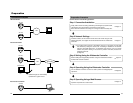
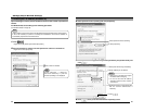
^
Focal length adjustment ring
Use the fastening screw adjustment ring to
set the image size and fix it with fastening
screw. (
☞
Page 24)
&
Focus ring
Use the fastening screw adjustment ring to
set the focus and fix it with fastening screw.
(
☞
Page 24)
Video setting switch
*
[D/N - ON/OFF] Easy Day & Night switch
To capture a subject with continually chang-
ing brightness (day/night), set this switch to
“ON”. The camera automatically captures the
image in color when the subject is bright, and
in black and white mode when it is dark.
(Default setting: OFF)
Caution
The Easy Day & Night feature on this
camera uses a sensitized black and white
mode unlike other black and white
surveillance cameras that use infra-red
lighting.
(
[FOCUS ADJ. - ON/OFF] focus adjustment
switch
When adjusting the focus during installation,
setting this switch to “ON” will open the
iris.(Default setting: OFF) (
☞
page 24)
)
[AGC - ON/OFF] Auto-gain control switch
Setting this switch to “ON” automatically in
creases the sensitivity even when the bright
ness of the subject is insufficient.
(Default setting: ON)
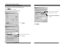
⁄
[BLC - ON/OFF] Backlight Compensation
switch
Setting this switch to “ON” opens the iris even
in backlight conditions, making the subject
easier to view.
(Default setting: OFF)
¤
[AUTO/MANU] White Balance Automatic/
Manual switch
For selecting whether to adjust the white bal-
ance automatically or manually.
(Default setting: AUTO)
‹
[R/B] Manual WHITE adjustment button
This button is pressed when manually adjust-
ing the white balance.
This feature is enabled when the “MANU” is
selected using
¤
[AUTO/MANU] switch.
Press the B button to increase the blue tint
and decrease the red tint.
›
[RESET] Manual WHITE reset button
When this button is pressed, the value of the
white balance adjusted manually is reset to
the default value.
fi
[SPOT CORRECTION] White-spot correc-
tion button
When this button is pressed, white spots are
corrected.
For instructions on correcting white-spots, see
“About White-spot correction”.
(
☞
page 26)
%
[10BASE-T/100BASE-TX] 10BASE-T/
100BASE-TX Terminal
This is a 10BASE-T/100BASE-TX terminal.
It is used for connecting to the network via
LAN cables. (
☞
Page 20)
Signal Name
Alarm Output
Alarm Input
Alarm Output 1
Alarm Output 2
Alarm Input 1
Alarm Input 2
GND
1
2
3
4
5
Pin No.