


8
PC Specifications
OS : Windows 2000 Professional (SP1 or later)
Windows 2000 Server (SP1 or later)
Windows XP Home Edition (SP1 or later)
Windows XP Professional (SP1 or later)
CPU :
Equivalent to or higher than Pentium 3, 500 MHz (Pentium4, 3.2 GHz
recommended)
Memory : 128 MB and above (1 GB recommended)
Hard Disk Space : 20 MB and above
Display and Video Card : 1024 x 768 pixels or higher, true color (24 bit or 32 bit)
*VRAM 8MB and above (256 MB and above recommended)
LAN Environment
• 10BASE-T/100BASE-TX networks mutually connected by IEEE802.3-compliant Hubs.
CF Card
• Refer to Page 19 for a list of tested CF cards.
Operating Environment
Latest Updates
To upgrade the software version or obtain any other latest information, please visit the following website:
http://www.jvc-victor.co.jp/english/pro/vnetworks/index-e.html
Introduction
Operating Precautions (Continued)
Notes
• General users of Windows XP or restricted users of Windows 2000 are not allowed to add/
delete V.Networks or change snapshot and recording settings.
• The PC specifications above are only reference values for smooth operation of this application,
and are not meant to guarantee operation of this application. Even if the PC satisfies the
technical requirements, problems may occur depending on its usage.
Caution
If the OS specifications of the PC to be used are higher, they precede those described above.
How to Use This Manual
Characters and symbols used in this manual
Caution Points to pay attention to during operation.
Note Details for reference, such as functions or constraints during use.
☞ Pages or items to refer to.
* JVC shall not be held liable for any loss or damage to the customer or any claim from a third
party arising from the use of this software.
Specifications of this software are subject to alteration for improvement without prior notice.
All product names that appear in this document are the trademarks or registered trademarks
of their respective companies. Marks and symbols such as ™,® and © do not appear in this
document.
9
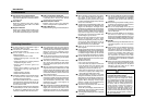
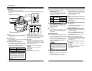
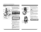
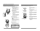
Camera
Name and Function of Parts
1
Safety cable mounting hole
This hole is mounted to the ceiling slab or
channel. (Safety cable not included.)
Caution
To avoid unforeseen accidents, attach the
safety cable. Otherwise, there is nothing to
prevent the camera from falling should it
come loose.
2
Mounting holes
These holes are used to mount the camera
body to the ceiling. When using a 4 inch
square electrical box, the 2 holes diagonally
across are used to fix the box in place.
(
☞
Page 21)
3
Dome Cover
The dome cover is fragile. Take care when
handling it.
4
Plate for depressing cables
5
Cable extraction hole
This hole is used to extract cables from the
side of the camera without opening holes in
the ceiling.
6
Input Power cable
To input DC 12 V or AC 24 V power.
The AC 24 V power supply should conform
to the following : Class 2 only (For USA), Iso-
lated power supply only (For Europe).
7
Video signal output connector (BNC)
This BNC connector outputs a composite
video signal. Connect this to the video input
connector of a video monitor, switcher, etc.
(
☞
Page 23)
Output is restricted signal in the NTSC for-
mat only.
2
3
1
7
6
4
5