


20
Preparation (Step 1 Connection/Installation)
1-2 Mounting the Camera to the Ceiling (Continued)
2. Installation
Note
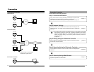
When using 100 BASE-TX, ensure to use
a Category 5 (or higher) cable.
Caution
The use of a crossover cable may not be
supported by certain LAN boards on some
rare occasions. As such, please check your
LAN board specifications before connection.
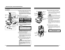
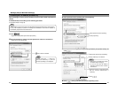
1.
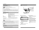
Attach the safety cable to the ceiling
slab. (Safety cable not included)
Attach the safety cable that has already been
attached to the camera to the ceiling slab or
channel. Make sure that the wire is attached
securely.
2.
Connect the video signal cable.
Connect the coaxial cables (BNC) to the video
signal output connector (BNC).
Safety
cable
Video signal
cable
Attach to ceiling slab
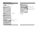
Insulation tape
Input power supply
cable
Solder or
crimp
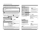
5.
1.
2 .
4 .
3 .
Alarm signal cable
LAN cable
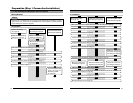
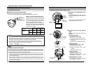
Alarm Signal Cable
10 BASE -T/100 BASE-TX
Ter minal
LAN cable
Cable
Maximum length (No
cable compensator)
RG-59 200m (650 ft)
RG-6 350m (1140 ft)
RG-11 450m (1470 ft)
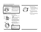
4.
Connect the alarm terminal
Connect the alarm cable wired in step 5 of
Preparations (
☞
page 17) to the alarm
terminal of camera unit. Pass the cable under
the plate for depressing cables same as step
3 before connecting.
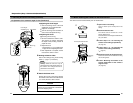
5.
Connect the input power supply cable.
Connect the cable protruding from the ceiling
to the input power cable. (
☞
Page 22)
3.
Connect the LAN cable
Pass the LAN cable coming out from the
ceiling under the plate for depressing cables,
connect it to the 10BASE-T/100BASE-TX
Terminal of the camera unit.
Note
The input power cable uses materials
similar to those of machinery wiring, so
wrap the cable with insulation tape to
prevent it from becoming damaged when
mounting the camera.
Use durable wiring for the input power
cable.
21
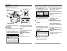
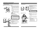
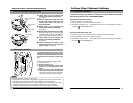
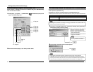
6.
Wrap insulation tape around cables.
As shown in the diagram to the left, wrap
insulation tape around the input power cable
connection and BNC connector. Insert the
cables into the hole in the ceiling.
7.
Point the camera in the direction you
wish to capture.
Point the camera so that the Horizontal Lock
screw is facing the direction you wish to
capture. The camera can be adjusted ±60˚
horizontally to either side of the Horizontal
Lock screw.
8.
Mount the camera to the ceiling.
Use M4-sized (No. 8) screws/bolts or wood
screws (4.1mm, 1/8 inches) to secure the
camera in four places when mounting to the
ceiling or wall.
Input power
cable
connection
BNC
Connector
Wrap with
tape
Wrap with
tape
6.
LAN cable
Alarm signal
cable
Mounting
holes
Mounting
holes
Horizontal
Lock screw
Screws
7.
8.
Note
Wrapping the wires with insulation tape
improves handling as well as reducing
interference.
Caution
Tighten all screws securely. Otherwise the
camera may come loose and fall.