


© National Instruments Corporation 3-1 NI 1450 Series Compact Vision System User Manual
3
LEDs, DIP Switches, and
Connectors
This chapter provides information about the location and functionality of
the LED indicators, DIP switches, and connectors on the NI 1450. The
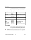
Connectors section provides signal names and descriptions for each
connector.
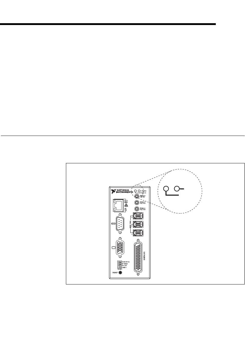
LED Indicators
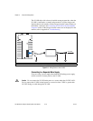
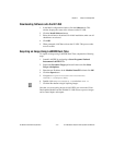
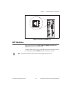
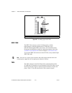
Figure 3-1 shows the location of the POWER OK and STATUS LEDs on
the NI 1450.
Figure 3-1. POWER OK and STATUS LEDs
Refer to Appendix A, Troubleshooting, for information about
troubleshooting LEDs.
STATUS
POWER OK
NI 1454
Compact Vision System