Chapter 3 LEDs, DIP Switches, and Connectors
© National Instruments Corporation 3-13 NI 1450 Series Compact Vision System User Manual
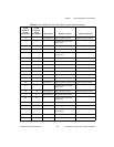
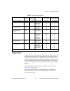
4 5 TTL Output 1 Pulse generator output General-purpose output
5 6 C Common of the NI 1450
main power
—
6 7 TTL Output 2 Pulse generator output General-purpose output
7 8 TTL Output 3 Pulse generator output General-purpose output
8 6 C Common of the NI 1450
main power
—
9 NC NC No connect —
10 17 Viso Isolated power —
11 18 Ciso Isolated common —
12 19 ISO Output 0 General-purpose output —
13 35 ISO Output 1 General-purpose output —
14 34 Ciso Isolated common —
15 9 ISO Input 0 Input port, Data(0)
—
16 2 TTL Input 1 Pulse generator trigger input General-purpose input
17 3 C Common of the NI 1450
main power
—
18 20 TTL Output 4 Pulse generator output General-purpose output
19 21 TTL Output 5 General-purpose output —
20 22 C Common of the NI 1450
main power
—
21 23 TTL Output 6 General-purpose output —
22 24 TTL Output 7 General-purpose output —
23 22 C Common of the NI 1450
main power
—
24 NC NC No connect —
25 33 Viso Isolated power —
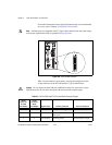
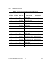
Table 3-5. 44-Pin DSUB and 37-Pin Terminal Block Connector Signals (Continued)
44-Pin
DSUB on
NI 1450
Pin Number
37-Pin
Terminal
Block
Pin Number
Signal Name Primary Function Alternate Function


