


Chapter 3 LEDs, DIP Switches, and Connectors
© National Instruments Corporation 3-9 NI 1450 Series Compact Vision System User Manual
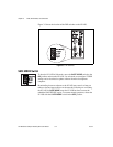
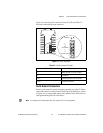
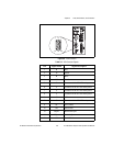
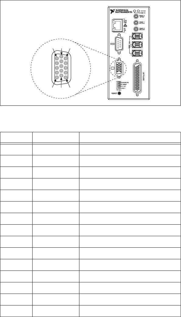
Figure 3-6. VGA Connector
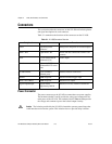
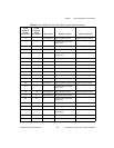
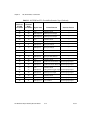
Table 3-3. VGA Connector Signals
Pin Signal Name Signal Description
1 R Red
2 G Green
3 B Blue
4 NC No Connect
5 C Common of the NI 1450 main power
6 C Common of the NI 1450 main power
7 C Common of the NI 1450 main power
8 C Common of the NI 1450 main power
9 +5V +5V
10 C Common of the NI 1450 main power
11 NC No Connect
12 SD Serial Data
13 HSync Horizontal Sync
14 VSync Vertical Sync
15 SC Serial Clock
1611
51015
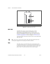
NI 1454
Compact Vision System