


Chapter 3 LEDs, DIP Switches, and Connectors
NI 1450 Series Compact Vision System User Manual 3-6 ni.com
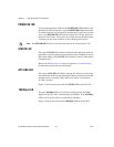
Connectors
This section describes the connectors on the NI 1450 and includes pinouts
and signal descriptions for each connector.
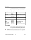
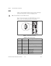
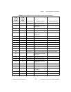
Table 3-1 summarizes the functions of the connectors on the NI 1450.
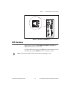
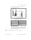
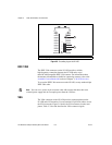
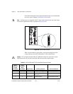
Power Connector
The power connector on the NI 1450 accommodates two power supplies.
The terminals labeled V and C provide the voltage and common for the
main power of the NI 1450. The terminals labeled Viso and Ciso provide
the voltage and common to power the isolated output circuitry.
Caution The isolation provided by the NI 1450 is intended to prevent ground loops that
could introduce noise into the system. This isolation does not provide safety isolation.
Table 3-1. NI 1450 Connectors Overview
Peripheral External Connectors Function
Power 4-position power
connector
Main power and power for isolated outputs
IEEE 1394a 6-pin IEEE 1394 Power and data connection to IEEE 1394
cameras
VGA 15-pin female DSUB
(standard VGA)
Video output
Serial 9-pin male DSUB
(standard RS-232 serial
port)
COM1
10/100 Ethernet RJ-45 (standard
Ethernet port)
Ethernet network connection
TRIG 0 SMB receptacle External isolated trigger input
TRIG 1 and TRIG 2 SMB receptacle External TTL output
Digital Input/Output 44-pin female
high-density DSUB
External TTL I/O; External isolated I/O