


Chapter 4 Digital I/O Functionality
NI 1450 Series Compact Vision System User Manual 4-14 ni.com
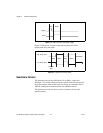
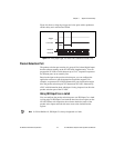
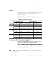
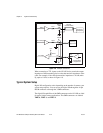
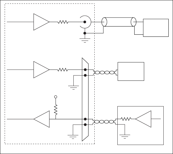
Figure 4-8. Example Connections
When connecting to TTL inputs on the NI 1450 device, match the output
impedance of the transmitting device to the characteristic impedance of the
cable. For example, if the cable characteristic impedance is 118 Ω, make
R
s
equal to 118 Ω, as shown in Figure 4-8.
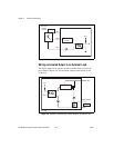
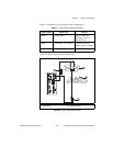
Typical System Setup
Digital I/O configuration varies depending on the number of cameras your
system setup requires. You can access the digital I/O through the 44-pin
DSUB connector or through the 3 SMB connectors.
The digital I/O capabilities of the SMB connectors on the NI 1450 are ideal
for typical single-camera applications. The SMB connectors are labeled
TRIG 0, TRIG 1, and TRIG 2.
TTL OUT(0)
Receiving
Equipment
TTL IN(0)
118 Ω
44-Pin
DSUB
3
2
16
17
62 kΩ
Transmitting
Equipment
R
S
TRIG 1
75 Ω
TRIG 1
SMB
RG-179
Coaxial Cable
+5 V
NI 1450
Receiving
Equipment