


Index
NI 1450 Series Compact Vision System User Manual I-4 ni.com
POWER OK LED, 3-2
power requirements specifications, B-1
power supply
connector, 3-6, 3-7
connector (table), 3-6
desktop, 2-1
earth ground, 3-7
separate main supply, 2-10
terminals (table), 3-7
wiring power, 2-9
wiring power (diagram), 2-10
product selection port, 4-7
(table), 4-8
professional services, C-1
programming examples, C-1
pulse delay, 4-5
pulse modes, 4-5
pulse width, 4-5
Q
quadrature encoder, 4-6
R
required hardware, 2-1
S
SAFE MODE DIP switch, 3-4
safety information, 2-4
safety specifications, B-4
serial number, 5-2
serial port, connector (table), 3-6
setup
multiple NI 1450s, 5-1
typical single-camera, 4-14
setup and configuration, 2-1
shutdown, 4-9
shutdown, disabling, 4-10
software
application, 1-4, 1-5
installing on development computer, 2-13
NI-IMAQ for IEEE 1394 Cameras, 1-4
software choices, 1-4
software drivers, C-1
sourcing output device
wiring, 4-11
diagram, 4-12
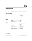
specifications
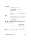
electromagnetic compatibility, B-4
environmental, B-4
memory, B-1
network, B-1
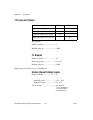
optically isolated inputs, B-2
optically isolated outputs, B-3
outputs, B-3
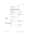
physical characteristics, B-3
power requirements, B-1
safety, B-4
TTL inputs, B-2
TTL outputs, B-2
STATUS LED, 3-2
STATUS LED error indications (table), A-3
subnet, 2-8, 5-2
support, technical, C-1
system integration services, C-1
T
technical support, C-1
telephone technical support, C-2
termincal block, 37-pin (table), 3-12
timed pulse output, 4-4
timed pulse output, initiating, 4-4
training, customer, C-1
transmission line effects, 4-13
TRIG 0
cable, 3-11
connector (table), 3-6