


Chapter 3 LEDs, DIP Switches, and Connectors
NI 1450 Series Compact Vision System User Manual 3-8 ni.com
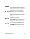
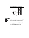
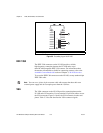
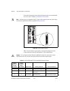
Figure 3-5. Grounding Lug on the NI 1450
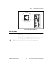
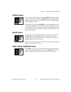
IEEE 1394
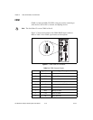
The IEEE 1394 connectors on the NI 1450 provide a reliable,
high-frequency connection between the NI 1450 and to up to
three DCAM-compatible IEEE 1394 cameras. For information about
the amount of bandwidth available for connecting cameras, refer to the
Available Camera Bandwidth section of Chapter 1, NI 1450 Overview.
To access the IEEE 1394 connectors on the NI 1450, use any standard 6-pin
IEEE 1394 cable.
Note You can use a 4-pin to 6-pin converter cable with cameras that have their own
external power supply and do not require power from the 1394 bus.
VGA
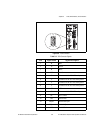
The VGA connector on the NI 1450 provides connection between the
NI 1450 and a VGA monitor. Use any standard 15-pin VGA cable to access
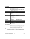
the VGA connector. Figure 3-6 shows the VGA connector location and
pinout. Table 3-3 lists and describes the VGA connector signals.
1 Grounding Lug 2 Power Connector
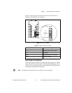
Viso
(5-30VDC)
C
V
(24VDC ±10%)
C
iso
POWER
1
2