


Chapter 4 Digital I/O Functionality
© National Instruments Corporation 4-3 NI 1450 Series Compact Vision System User Manual
Trigger Inputs
Trigger inputs are available from both TTL inputs and isolated inputs. You
can use these trigger inputs to synchronize the NI 1450 with an external
event, such as the assertion of a signal generated by a proximity sensor or
a PLC to indicate that an inspection item is passing in front of the camera.
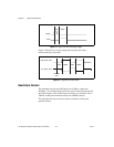
The NI 1450 uses this input to initiate a timed pulse that can be used for
camera control, lighting control, encoder pulse counting, and result output
timing.
For more information about creating a timed pulse output, refer to the
Timed Pulse Output section.
Alternatively, the ISO Input 5 signal can function as a latch input for
the product selection port, and all five trigger inputs can function as
general-purpose inputs.
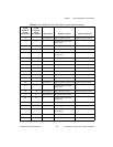
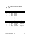
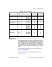
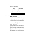
Table 4-2. Isolated Inputs and Outputs
Primary Function
Input or
Output
Number
Available
Signal Names
44-Pin DSUB
on NI 1450
Pin Number
37-Pin
Terminal Block
Pin Number
Trigger Input 3 TRIG 0
ISO Input 5
†
ISO Input 8
—
35
40
—
15
27
Quadrature Encoder Input 1 ISO Input 6
ISO Input 7
37
38
25
26
External Shutdown
Control
Input 1 ISO Input 11 44 31
Product Selection Port
†
Input 1 ISO Input 0
ISO Input 1
ISO Input 2
ISO Input 3
ISO Input 4
15
30
31
32
34
9
10
11
13
14
General-Purpose Input 2 ISO Input 9
ISO Input 10
41
43
29
30
General-Purpose Output 4 ISO Output 0
ISO Output 1
ISO Output 2
ISO Output 3
12
13
27
28
19
35
36
37
†
ISO Input 5 can also function as a latch for the product selection port.