


Chapter 4 Digital I/O Functionality
© National Instruments Corporation 4-13 NI 1450 Series Compact Vision System User Manual
Protecting Inductive Loads
When an inductive load, such as a relay or solenoid, is connected to an
output, a large counter-electromotive force may occur at switching time
due to energy stored in the inductive load. This flyback voltage can damage
the outputs and the power supply.
To limit flyback voltages at the inductive load, install a flyback diode across
the load. Mount the flyback diode as close to the load as possible. Use this
protection method if you connect any of the isolated outputs on the NI 1450
to an inductive load.
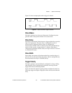
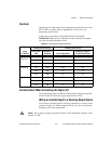
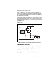
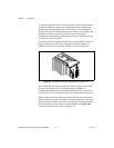
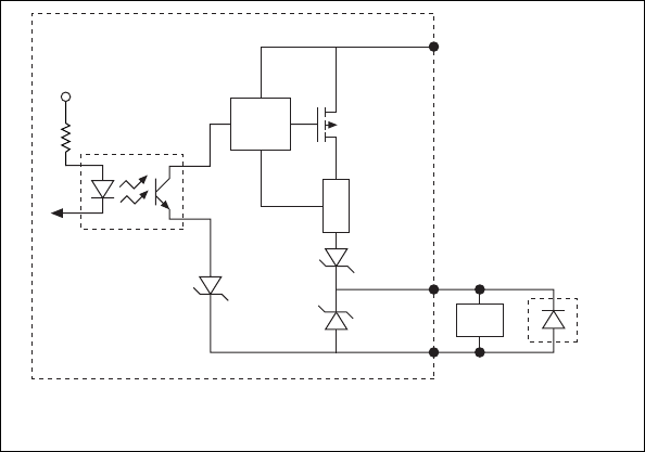
Figure 4-7 shows an example of using an external flyback diode to protect
inductive loads.
Figure 4-7. Example of Using an External Flyback Diode for Inductive Loads
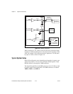
Transmission Line Effects
Transmission line effects can degrade the signals on the I/O cables and
cause instability. To minimize transmission line effects, use twisted-pair
wires with a characteristic impedance of 118Ω to connect external signals
to the 44-pin I/O DSUB connector. Use a 75Ω coaxial cable, such as
RG-179, to connect to the SMB connectors.
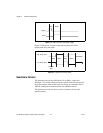
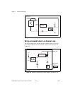
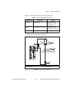
Figure 4-8 shows connections to the 44-pin DSUB connector and the
TRIG 0 SMB connector that minimize transmission line effects.
Digital
Output
Viso
Ciso
Vcc
NI 1450
External
Flyback
Diode for
Inductive Loads
Load