


Chapter 3 LEDs, DIP Switches, and Connectors
© National Instruments Corporation 3-7 NI 1450 Series Compact Vision System User Manual
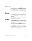
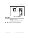
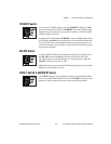
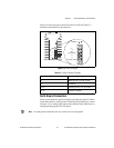
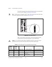
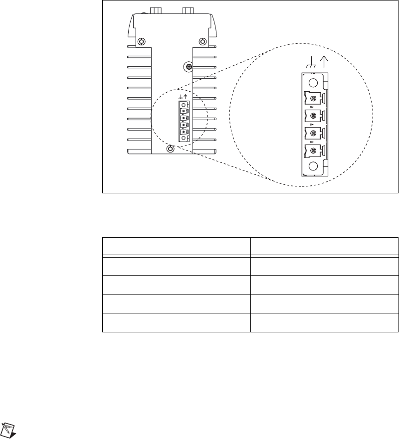
Figure 3-4 shows the power connector on the NI 1450, and Table 3-2
describes each terminal on the connector.
Figure 3-4. Power Connector
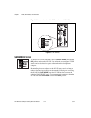
Earth Ground Connection
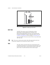
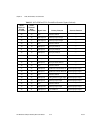
Some system setups may require using the grounding lug on the NI 1450 to
connect the chassis to earth ground. Connecting the grounding lug, shown
in Figure 3-5, to earth ground connects the common of the main power to
earth ground through the NI 1450 chassis.
Note An earth ground connection does not connect Ciso to earth ground.
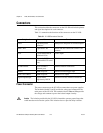
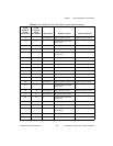
Table 3-2. Power Connector Terminals
Terminal Description
V Main power (24 VDC ±10%)
C Common
Viso Isolated power (5 to 30 VDC)
Ciso Isolated common
V
iso
(5-30 VDC)
C
C
iso
POWER
V
(24 VDC ±10%)
Viso
(5-30 VDC)
C
V
(24 VDC ±10%)
C
iso
POWER