


Chapter 3 LEDs, DIP Switches, and Connectors
NI 1450 Series Compact Vision System User Manual 3-12 ni.com
For detailed information about digital I/O functionality and recommended
use cases, refer to Chapter 4, Digital I/O Functionality.
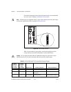
Note Isolated inputs are compatible with 5 V logic if the external circuit meets the voltage
and current requirements listed in Appendix B, Specifications.
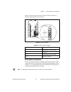
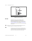
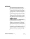
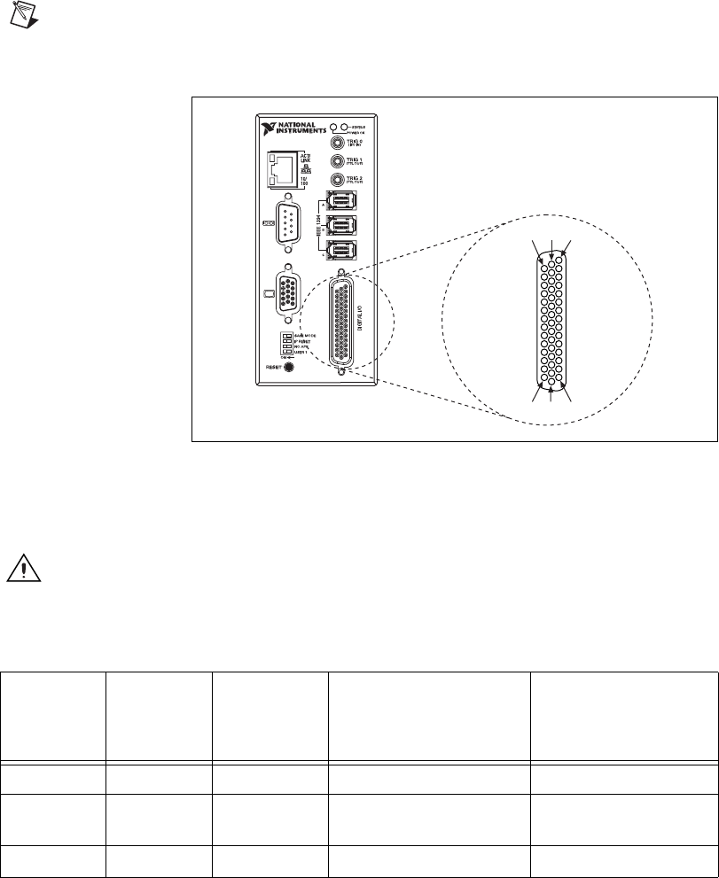
Figure 3-8. 44-Pin DSUB Connector
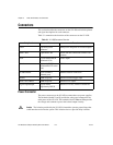
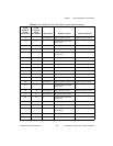
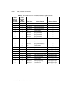
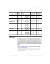
Table lists pin numbers, signal names, and signal descriptions for the
44-pin connector on the NI 1450 and the 37-pin terminal block.
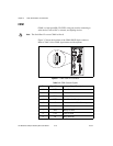
Caution Do not draw more than 500 mA combined from the Viso pins on the 44-pin
DSUB connector. Do not draw more than 100 mA from each isolated output.
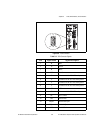
Table 3-5. 44-Pin DSUB and 37-Pin Terminal Block Connector Signals
44-Pin
DSUB on
NI 1450
Pin Number
37-Pin
Terminal
Block
Pin Number
Signal Name Primary Function Alternate Function
1 1 TTL Input 0 Pulse generator trigger input General-purpose input
2 3 C Common of the NI 1450
main power
—
3 4 TTL Output 0 Watchdog output General-purpose output
11631
153044
NI 1454
Compact Vision System