


13
Location and Function of Parts
5.1 BRC Series of Cameras
Location and Function of Parts
5
The following is a summary of the location and function of BRC-H700, BRC-Z700, BRC-Z330, and
BRC-300/300P parts.
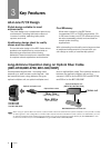
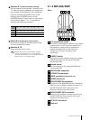
5.1.1 BRC-H700
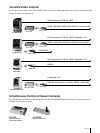
RGB/COMPONENT
VISCA RS-422
1 2 3 4 5 6 7 8 9
EXT SYNC IN
IR SELECT
75
1 2 3
DATA MIX
OFF ON
OFF ON
IN VISCA RS-232C OUT
DC IN 12V
R
RGB/COMPONENT
VISCA RS-422
1 2 3 4 5 6 7 8 9
EXT SYNC IN
IR SELECT
75
1 2 3
DATA MIX
OFF ON
OFF ON
IN VISCA RS-232C OUT
DC IN 12V
R
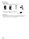
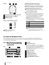
With the cable cover attached
1 2 3 4 5
6 7 8 9 10 11 12
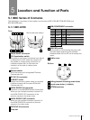
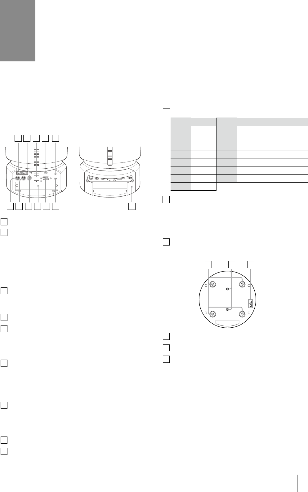
Rear
1
VISCA RS-422 connector
75 Ω termination switch
This switch is used when an external sync signal
is utilized. Set it to OFF when the camera is in
the middle of a daisy-chain connection of
multiple cameras. Set it to ON when the
camera is at the end of a daisy-chain
connection.
Remote sensor
This is the sensor for the supplied IR Remote
Commander Unit.
DC IN 12V connector
IR SELECT switch
Selects the camera number when you operate
multiple cameras with the same IR Remote
Commander Unit.
VISCA RS-232C IN connector
Connects to the RM-BR300 Remote Control Unit.
When you join multiple cameras, connect it to
the VISCA RS-232C OUT connector of the
previous camera in the daisy chain.
VISCA RS-232C OUT connector
When you join multiple cameras, connect it to
the VISCA RS-232C IN connector of the next
camera in the daisy chain.
EXT SYNC IN connector
Card slot
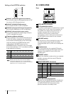
2
3
4
5
6
7
8
9
10
11
DATA MIX switch
Set the switch to ON to overlap the menu with
the video signal output from the installed
interface board. Set it to OFF not to overlap the
menu.
Cable cover
12
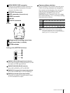
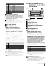
Bottom
13 14 15
13
14
15
Ceiling bracket mounting screw holes
Tripod screw holes
(1/4-20UNC)
BOTTOM switches
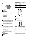
RGB/COMPONENT connector
Pin No. Signal Pin No. Signal
1 Pr/R 9 NC
2 Y/G 10 GND
3 Pb/B 11 GND
4 GND 12 NC
5 GND 13 HD-OUT
6 GND 14 Tri-level Sync/Bi-level VD
7 GND 15 NC
8 GND