


20
Location and Function of Parts
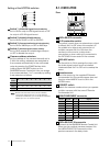
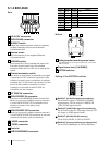
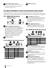
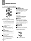
VISCA RS-232C OUT connector
When you join multiple cameras, connect it to
the VISCA RS-232C IN connector of the next
camera in the daisy chain.
CAMERA connector
10
11
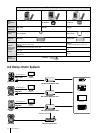
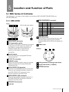
5.3 Optical Multiplex Cards and Optional Video Cards
The following provides information on the location and function of optical multiplex card parts and
optional video cards and optional video cards. The BRC Series allows you to choose from a wide range of
optional video cards. This versatility enables you to create flexible analog and digital system configurations.
5.3.1
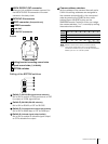
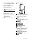
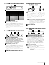
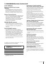
BRBK-H700 HD Optical
Multiplex Card
1
AUDIO IN L/R jacks (phono-type)
Input an audio signal (stereo) that is output
from the AUDIO OUT jacks on the BRBK-H700 HD
Optical Multiplex Card via an optical fiber
cable. The audio input on this board accepts
audio line signals only. When you input audio
signals from a microphone or similar device, it
should be connected with a microphone
amplifier so that audio signals with an
appropriate audio level can be input.
Optical connector
2
1 2
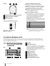
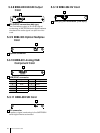
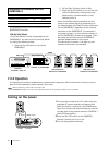
5.3.2
HFBK-HD1 HD Interface Board
1
MONITOR connector (D-sub 15-pin)
1 2 3
2
DIP switches (inside the cap)
When this interface board is inserted into the
camera or the BRU-H700 HD Optical Multiplex
Unit, the DIP switches cannot be used.
The parameters can be set from the menu of
the camera.
HD-SDI connector (BNC-type)
Supplies HD-SDI signals that conform to the
SMPTE292M serial digital interface standard.
The two connectors output the same signal.
3
Pin No. Signal Pin No. Signal
1 R/Pr (X) 9 NC
2 G/ Y (X) 10 GND
3 B/Pb (X) 11 NC
4 NC 12 NC
5 GND 13 HD
6 R/Pr (G) 14 VD/SYNC
7 G/Y (G) 15 NC
8 B/Pb (G)
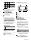
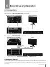
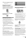
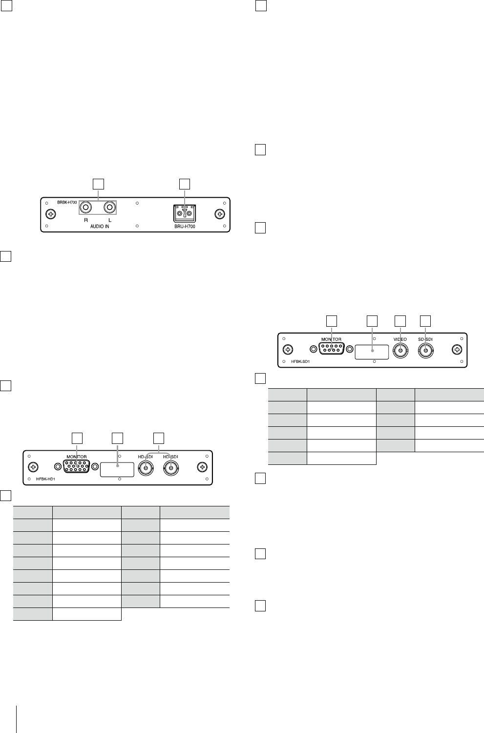
5.3.3
HFBK-SD1 SD Interface Board
1
MONITOR connector (D-sub 9-pin)
1 2 3 4
2
DIP switches (inside the cap)
When this interface board is inserted into the
camera or the BRU-H700 HD Optical Multiplex
Unit, the DIP switches cannot be used.
The parameters can be set from the menu of
the camera.
VIDEO connector (BNC-type)
Supplies analog composite signals. The aspect
ratio can be selected in the camera’s DOWN
CONVERTER menu.
SD-SDI connector (BNC-type)
Supplies down-converted SD-SDI signals that
conform to SMPTE259M (for 59.94i signal
format) and ITU-R BT.656 (for 50i signal format)
serial digital interface standards. The aspect
ratio can be selected with the camera’s DOWN
CONVERTER menu.
3
Pin No. Signal Pin No. Signal
1 GND 6 Composite/Y
2 GND 7 SYNC
3 R/Cr 8 GND
4 G/ Y 9
-
/C
5 B/Cb
4