


15
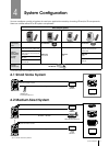
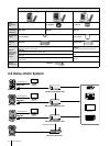
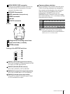
Location and Function of Parts
8
9
10
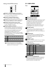
Bottom
14
15
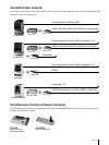
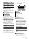
Ceiling bracket mounting screw holes
Tripod screw holes
(1/4-20UNC)
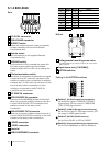
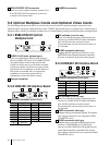
BOTTOM switches
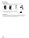
Setting of the BOTTOM switches
Switch 1 (59.94i/50i signal format selector)
Set to ON for output of 50i signal format, or OFF
for output of 59.94i signal format.
Switch 2 (RS-232C/RS-422 selector)
Set to ON for RS-422, or OFF for RS-232C.
Switch 3 (
Communication baud rate selector
)
Set to ON for 38400 bps, or OFF for 9600 bps.
Switch 4 (Infrared signal output switch)
Set to ON to enable an infrared signal output,
or OFF to disable the output.
1
2
3
4
5
11
12
13
14 15 16
16
O
N
1
2
3
4
O
N
1
2
3
4
1
2
3
4
5
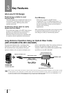
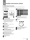
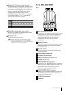
VISCA RS-232C OUT connector
When you join multiple cameras, connect it to
the VISCA RS-232C IN connector of the next
camera in the daisy chain.
EXT SYNC IN connector
VIDEO connector
(Composite out)
S-VIDEO connector
Card slot
DC IN 12V connector
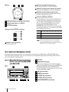
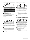
Camera address selectors
Set the address of the camera. Normally set to
0. With this setting, addresses are assigned to
the cameras automatically in the connected
order by pressing the POWER button while
holding down the RESET button on the
RM-BR300 Remote Control Unit. You can assign
the camera address, 1 to 7, manually by setting
these selectors as follows:
Please note that the same camera address
cannot be assigned to two or more different
cameras. Furthermore, you must set the switches
before you turn on camera power.
Note
Switch 4 is not used.
Camera
0 1 2 3 4 5 6 7
address
Switch 1
OFF ON OFF ON OFF ON OFF ON
Switch 2
OFF OFF ON ON OFF OFF ON ON
Switch 3
OFF OFF OFF OFF ON ON ON ON