


2-17
HDW-F900 P1E2
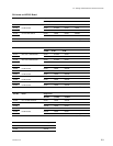
M1.4 x 2.5
M1.4 x 2.5
M1.4 x 2.5
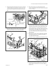
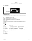
Antenna flexible board (FL-260)
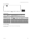
Notch of
cam plate (A)
Cassette
guide pin
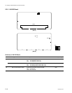
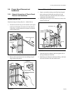
* The frame of the unit is not shown in the figure.
Notch
Round hole
of stage
Stage
Lever
Eject arm
roller (White)
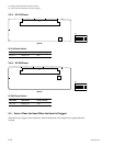
Joint arm
Roller (white) of step 4
Cassette guide pin
0.5 mm
Joint arm
Roller (White)
Edge of mechanism
deck assembly
Cam plate (A)
Lock roller (White)
6. Move the cam plate (A) on the right side of the
cassette compartment in the arrow direction by manual
as far as it will go.
7. Hold the portion of the cassette compartment shown in
the figure, and attach the cassette compartment in the
chassis so that the two cassette guide pins enter into
the round holes of the stage. Next, check that the white
roller of the eject arm which position is adjusted at
step 4 fits with the notch of the cam plate (A) on the
right side plate.
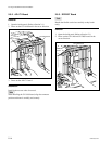
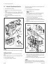
8. Push the lever of the cassette compartment and make
sure that the stage moves up and down smoothly. If
not, check again from step 4.
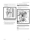
9. Attach the cassette compartment with the three screws.
10. Reconnect the antenna flexible board FL-260 to the
CCM-33B board of the DC-DC converter. (Refer to
Section 2-7.)
2-6. Cassette Compartment Aseembly Removal and Installation
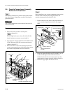
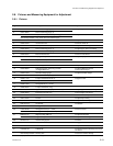
4. Adjust the position of the joint arm to have a clearance
of 0.5mm between the perimeter of white roller of the
joint arm and the edge of the mechanism deck assem-
bly.
5. Raise the white lock roller of the cassette compartment
in the arrow direction to set it to the raised status.