


Appendix
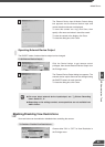
74LVC14
+3.3V
0.1µF
10kΩ 10kΩ
10kΩ
Internal controller
Input terminals
In1, In2
Output terminals
Out1, Out2
+
-
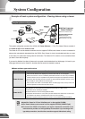
External Device I/O Terminals
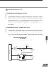
External Device Input Terminals (In1, In2)
The external device input terminals consist of 2 terminals (In1 and In2), one of which is '+' (red) and
another is '-' (black). The '-' terminal is grounded on the inside of the main unit. By connecting two
cables to the + and - terminals and then electrically short-circuiting across the terminals (ON) or
separating the connection (OFF), an interrupt can be generated for the internal controller. See "Picture
Recording and External Device I/O Settings Page" (→ P.46) for information on the settings.
Connect any sensors and switches to terminals with electrically separate GND terminals and
power supplies.
External Device Output Terminals (Out1, Out2)
The external device output terminals consist of 2 white terminals (Out1 and Out2). Both terminal
combinations are peers. The Internal controller switches the two output terminals to disconnected
or connected condition. The output terminals use optocouplers and are separate from the internal
circuit in the VB150. Loads connected to the output terminals should be within the following
ratings:
Rating across the output terminals
DC : Up to 50V
Continuous load current: 200 mA
■Internal Connection Chart
102