


1. Connecting the camera
Dc In 13V
In Out
100/10BT
CC1
RS232C
Video In
Ethernet
CC2 V1 V2 V3 V4
Slot-A
Slot-B
12 21
A B A B
Video cable(RCA)
RS-232C cable
RS-232C cable
VB150 Rear panel
Camera
Video cable(RCA)
AC adapter
AC cable
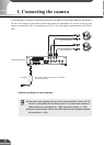
At this stage, please do not plug the AC adapter
into the wall outlet yet.
VC-C4
C
OM
MU
NI
CA
TI
ON
CAM
ERA
f:
4
-
6
4
m
m
1
:
1
.
4
-
2
.
8
Camera
VC-C4
C
OMM
U
NIC
AT
I
ON C
A
ME
RA
f
:
4
-
6
4
m
m
1
:
1
.
4
-
2
.
8
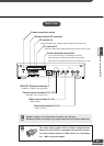
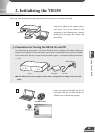
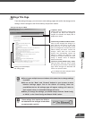
In this description, we begin by connecting 2 cameras to the VB150. The RS-232C cables are connected to
the CC1 and CC2 port on the VB150 and the video cables are connected to V1 and V2. In this way, one
camera is connected to CC1-V1 and the other to CC2-V2. The video cable is supplied with the VC-C4/VC-
C4R.
27
c
Note
● The video cable supplied with the Canon Communication Camera VC-C4/
VC-C4R, is compatible with the RCA pin-jack. To connect these cameras to
a BNC socket, use a third party Pin → BNC conversion adapter. (→ P.22)
● Canon Communication Camera VC-C4/VC-C4Rs can be cascade-connected
and controlled (→ P.42).
Camera connection is now complete.