


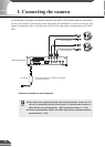

Before Using the VB150
1
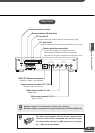
Dc In 13V
In Out
100/10BT
CC1
RS232C
Video In
Ethernet
CC2 V1 V2 V3 V4
Slot-A
Slot-B
12 21
A B A B
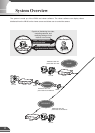
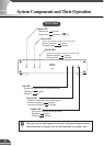
Power connection socket
External device I/O terminals
PC card slot A
(supports modem card, wireless LAN card and flash memory card)
PC card slot B
(supports modem card, wireless LAN card and flash memory card)
Factory defaults reset switch
You can return all settings on the VB150 to the factory
default settings by holding down this button with a pointed
object and as you plug the AC adapter into the wall outlet (→P.108).
100/10 BT Ethernet connector
(100Base-TX, 10Base-T auto-negotiation)
Camera control connector CC1, CC2
(RS-232C, with one touch lock)
Video input sockets V1, V2
(RCA pin-jack)
Video input sockets V3, V4
(BNC connector)
e
Tip
The video cable supplied with the Canon Communication
Camera VC-C4/VC-C4R is compatible with the RCA pin-jack.
To connect these cameras to a BNC socket, use a third party
Pin → BNC conversion adapter.
Rear View
c
Note
● Refer to page 111 for information on how to use a PC card.
● Camera control connectors can only be used for the VC-C4/VC-C4R/NU-700.
22