


2-6
Cisco UCS C210 Server Installation and Service Guide
OL-20887-02
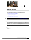
Chapter
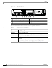
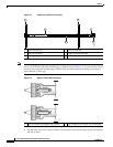
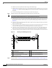
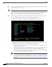
Figure 2-2 Attaching a Slide-Rail Assembly
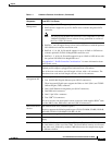
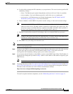
Note The mounting pegs that protrude through the rack-post holes are designed to fit round or square #12-24
holes, or #10-32 holes when the mounting peg is compressed (see
Figure 2-3). If your rack has #10-32
rack-post holes, align the mounting pegs with the holes and then compress the spring-loaded pegs to
expose the #10-32 inner peg.
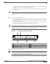
Figure 2-3 Spring-Loaded Mounting Pegs
c. Pull the inner slide rails on each assembly out toward the rack front until they hit the internal stops
and lock in place.
1 Front-left rack post 2 Rear-left rack post
3 Slide-rail assembly 4 Length-adjustment bracket
5 Locking clip (one on each end of assembly) 6 Mounting pegs (two on each end of assembly)
1
3 5
2
64
195968
1 Pegs in standard (uncompressed) position 2 Pegs compressed to expose 10-32 inner peg
330245
1
2