


3-13
Cisco UCS C210 Server Installation and Service Guide
OL-20887-02
Chapter
Installing or Replacing Components
Warning
This unit might have more than one power cord. To reduce the risk of electric shock, disconnect the
two power supply cords before servicing the unit.
Statement 14
Warning
Blank faceplates and cover panels serve three important functions: they prevent exposure to
hazardous voltages and currents inside the chassis; they contain electromagnetic interference (EMI)
that might disrupt other equipment; and they direct the flow of cooling air through the chassis. Do not
operate the system unless all cards, faceplates, front covers, and rear covers are in place.
Statement 1029
Caution When handling server components, wear an ESD strap to avoid damage.
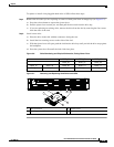
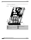
Tip You can press the Locator button on the front panel to turn on a flashing Locator LED on the server front
and rear panels. This button allows you to locate the specific server that you are servicing when you go
to the rear of the rack. See the “Status LEDs” section on page 3-2 for locations of the LEDs.
This section describes how to remove and replace server components. This section includes the following
topics:
• Installing Hard Drives and Solid State Drives, page 3-14
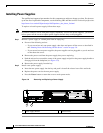
• Installing Power Supplies, page 3-16
• Installing a DVD Drive, page 3-17
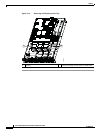
• Installing a Fan Tray, page 3-19
• Installing DIMMs, page 3-21
• Installing CPUs and Heatsinks, page 3-26
• Installing a Motherboard CMOS Battery, page 3-29
• Installing a Trusted Platform Module (TPM), page 3-30
• Replacing a PCIe Riser Card Assembly, page 3-32
• Replacing a PCIe Card, page 3-34
• Replacing a SAS Extender or SAS Expander, page 3-40
• Replacing an LSI MegaRAID Battery Backup Unit, page 3-42
• Installing a Mezzanine Card, page 3-44